
User's Manual

TECHNISONIC INDUSTRIES LIMITED
www.til.ca
TMS-100 90-6R/8.33
Installation & Operating Instructions
TiL 02RE301 Rev B
1-9
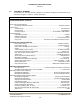
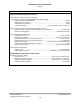
1.2 TECHNICAL SUMMARY
A summary of the relevant electrical, operational, mechanical and physical characteristics of the
transceiver are given in Table 1.1, Leading Particulars.
TABLE 1.1 LEADING PARTICULARS
TRANSCEIVER MODEL 90-6R/8.33:
Power Source Requirements:
DC Voltage (Negative Ground) ....................................................................... 13.75Vdc Nominal
Input Current:
Transmit Mode ...................................................................................................... 5.0A maximum
Receive Mode ....................................................................................................... 1.5A maximum
Frequency Range ........................................................................... 117.975MHz to 138.000MHz
Channel Spacing:
Narrowband (Normal)....................................................................................................... 8.33kHz
Wideband (Normal)............................................................................................................. 25kHz
Frequency Selection..................................................................................... Six Preset Channels
Duty Cycle............................................................... One Minute Transmit/Four Minutes Receive
TRANSMITTER CHARACTERISTICS:
Power Output (FCC) .....................................................…………………...... 10 Watts maximum
Power Output (ICAN) ......................................................…………………...... 8 Watts maximum
Output Power Stability After One Minute ........................................................................ ±1 Watt
VSWR ..................................................................................................................................... 4:1
Carrier Stability (-40°C to +55°C) ............... .................................................. ±1,000Hz maximum
Incidental FM and PM Due to Modulation ............................................................... ±100Hz max.
Rise Time to 90% of Rated Power ............................................................. 100milliseconds max.
Audio Input .................................................................................................. 50millivolts to 2Vrms
Speech Processor Dynamic Range ..................................................................... 35dB minimum
Modulation Capability .................................................................................................. Up to 95%
Audio Distortion (with 90% modulation) ............................................................... 10% maximum
Audio Frequency Response .............................................................. 300Hz to 2,500Hz, +1,-3dB
Spurious Emissions ........................................................................................ 60dB below carrier
Hum and Noise Level .................................................................... 45dB below modulated carrier
RECEIVER CHARACTERISTICS:
RF Input Circuit: ....................................................... 50-ohms unbalanced, VSWR 2:1 maximum
Sensitivity (12dB SINAD) 1kHz, 30% modulation ................................................... 1.8 microvolts
Selectivity, 25kHz Channel Spacing:
Bandwidth at 6dB Points .................................................................... More than 15kHz(±7.5kHz)
Bandwidth at 60dB Points .................................................................. Less than 22kH(±11.0kHz)
Selectivity, 8.33kHz Channel Spacing Option:
Bandwidth at 6dB Points ....................................................................... More than 10kHz(±5kHz)
Bandwidth at 60dB Points .................................................................. Less than 15kHz(±7.5kHz)
Adjacent Channel Selectivity ................................................................................... At least 80dB
Pass Band Symmetry ........................................................................................... 15% maximum
IF Band Pass Ripple Between -6dB Points ........................................................... 2dB maximum
Spurious Response Attenuation .............................................................................. At least 90dB
Frequency Stability (-40°C to +55°C) ............. ...................................................... ±1,000Hz max.
AGC Characteristics With RF Input Signal .................................................. 5 microvolts to 1 volt
Audio Level:........................................................................................................................... ±3dB