
User's Manual
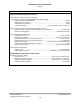

TECHNISONIC INDUSTRIES LIMITED
www.til.ca
TMS-100 90-6R/8.33
Installation & Operating Instructions
TiL 02RE301 Rev B
1-2
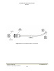
The microphone dc supply for the microphone is supplied by the transceiver. The
mounting bracket, provided with the microphone, should be mounted in a convenient
location near the transceiver. A small screwdriver which can be used for releasing the
modular plug located in the microphone head is supplied with the microphone. A
replacement plug-in microphone cord, P/N 963299-1, is available for this microphone.
This cord is supplied with a modular microphone plug on one end and a three-pin DIN
connector on the other to mate with the Model 90-6R/8.33 Transceiver.
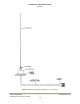
(e) Antenna Assembly, Part Number 861910-1, is supplied complete as a kit which includes
the following items: Antenna Base, which includes a mounting pad, together with a pad,
braid nut, sleeve and clamp for termination of the antenna RF cable. The Antenna Rod is
supplied with an Allen Wrench for adjustment of its set screws. The Antenna RF Cable is
a ten-metre length RG58/U coaxial cable terminated at one end by an UHF, male
contact, connector which mates with the UHF, female contact, antenna connector located
at the right-rear of the transceiver. The antenna may be mounted on any flat surface,
roof, cowl, fender or rear deck of a vehicle, however, rooftop mounting is recommended
for best performance. A general view of the antenna assembly is given in Figure 1.5.
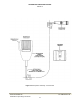
(f) A programming cable, TiL Part No. 013508-1 is included. This cable must be temporarily
connected from header jack J4 inside the radio to the serial port of a computer in order to
program frequency information into the transceiver. See Section 2 of this document for
frequency programming details.
1.1.2 Modes of Operation
The transceiver may be operated in either of two modes; transmit or receive, as selected by the
Press-to-Talk (PTT) switch on the microphone:
(1) Transmit Mode - When the PTT switch on the microphone is depressed, the transceiver
will operate in the transmit mode. The PTT signal line is grounded by the microphone
switch via the microphone lead and the MIC/PTT connector to the transceiver. The Tx
ON yellow LED will go “ON”, indicating that the transmitter is activated.
Transmission will occur on one of the six preset channel frequencies, determined by the
setting of the CHANNEL SWITCH. The appropriate CHANNEL INDICATOR green LED
1, 2, 3, 4, 5 or 6, will be ON, indicating the channel selected.
(2) Receive Mode - When the PTT switch on the microphone is released, the transceiver will
operate in the receive mode. The Tx ON yellow LED will go OFF, indicating that the
transmitter is de-activated. Reception on one of the six preset channel frequencies, as
selected by the CHANNEL SWITCH will occur.
The appropriate CHANNEL INDICATOR green LED 1, 2, 3, 4, 5, or 6, will be ON,
indicating the channel selected. The setting of the SQUELCH CONTROL determines the
squelch threshold level. When the SQUELCH CONTROL is adjusted in the counter-
clockwise direction, the SQUELCH INDICATOR green LED will go ON, indicating that the
squelch circuit is connecting the demodulated audio to the VOLUME CONTROL. The
setting of the VOLUME CONTROL determines the audio level produced from the internal
loudspeaker. When the VOLUME CONTROL is adjusted in the clockwise direction, the
audio level will increase.