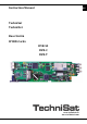
Instruction Manual EN TechniSat TechniNet Base Unit & IP IRD-Cards DVB-S2 DVB-C DVB-T www.technisat.de www.technisat.
EN Content 1 Safety advice.................................................................................................................................. 4 2 2.1 2.2 General ............................................................................................................................................ 6 Description .........................................................................................................................................................
4.6.3.2 4.6.3.3 4.6.3.4 4.6.4 4.6.5 4.6.5.1 4.6.6 5 5.1 5.2 5.3 5.4 ASI2/SDI Output ........................................................................................................................................... 42 Decoder Play................................................................................................................................................... 43 Decoder Config ..........................................................................................................
Safety advice EN 1 For your own safety you should read this first and carefully – please pay attention to the given advice before you start operating the device. All assembling and installations have to be carried out by professional staff. Professionals are persons who have an extended knowledge in the area of Sat Equipment installations and are also familiar with the safety and emergency standards. In addition they should be familiar with governmental rules and standards (e.g.
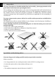
> The device may only be kept in rooms (away from radiated heat or heat sources), where, EN even if the climatic conditions change, the permissible surrounding temperatures can be assured. > Do not subject the set to any spray or dripping water.. > Liquid-filled objects are not allowed to be placed on the set. > Only mount it to vertical surfaces. > Keep the ventilation slots clear (30 cm each from the top and bottom). > Ensure good ventilation (do not fit in cupboards or niches).
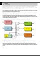
EN 2 2.1 General Description The TechniNet IP IRD cards receive a large number of channels of the DVB-S/S2, DVB-C or DVB-T signal and transmit those as IPTV or TSoIP via Ethernet 100BaseT interfaces in your IP based network. As network protocol UDP or RTP are used. The equipment is fitted with a TWIN-CI interface which can, with the aid of up to two CAMs, encrypt the channels directly through the card.
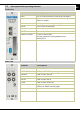
2.2 Description of the operating elements Front view Element Description LAN RJ-45 socket, network connection, full-duplex POWER LED, operational voltage display TS/IP LOCK IP RST RESET Remote Control Common Interface RJ-45 socket, TSoIP-connection, half - duplex, Input or output LED, Tuner lock display Button, IP Reset Button, Card Reset 15pol.
Bringing into service EN 3 ESD-safety During operation of the device the ESD-safeguards in accordance with DIN EN 100 015-1 have to be observed. (Induced by a potential equalization between chassis and equipment material as well as housing materials through high resistance (approx. 1 MOhm), for example with a standard ESD-wristband). 3.1 Assembling The operation of the module is solely carried out in one of the various slots of the TechniNet IP base unit.
3.2.3 Handset EN The 15pol. D-Sub Connector should be used for the connection of the programmer unit (0000/5971) via cable. 3.2.4 TUNER IN After assembling the module into the base unit such as described in Point 4.1 the SAT-ZF connection has to be connected with the TUNER IN F- connector. The device is ready for reception immediately. 3.2.5 LOOP THRU The SAT-ZF level chosen by a card for forwarding to another card rests against the Fconnector LOOP THRU. 3.2.
Programming EN 4 The configuration of the card is possible in three different ways: 1. Programmer (art. No. 0000/5971) connected via cable 2. TMS - TechniNet Management Software 3. Web-Interface Details of operation of the TMS are available in the TMS manual.
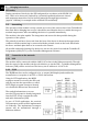
4.1 Programmer EN 4.1.1 Menu structure Welcome 0000/5972 IP:10.10.110.101 Main Menu Inputs Inputs Status Main Menu -> Inputs -> ASI Unlock Tuner 42.584528M IP In:100M IP in:Unlock Inputs RSSI -> Strength -37.0dBm C/N 15.2dB Eb_NO 12.2dB BER 0.0e-8 Inputs DVB-S2 -> LNB Frequency 10600MHz (nur 0000/5972) Satellite Frequency 11836MHz Symbol Rate 27000KBaud LNB Voltage 18V LNB 22kHz Off DiSEqC DiSEqC Off 11 Nur vorhanden, wenn IP/TS Anschluss als Inputconfigured ist.
EN Main menu Inputs QAM -> Constellation 256 Inputs (nur 0000/5975) Frequency 442000KHz Symbol Rate 6900KBaud Inputs COFDM -> Frequency 474.000MHz (nur 0000/5976) Band Width 8M Inputs Ethernet -> Stream IP Addr 10.10.111.1 Nur vorhanden, wenn IP/TS Anschluss als Inputconfigured ist. Stream Netmask 255.255.255.0 Stream Gateway 10.10.70.1 Stream Mac Address 00:06:f4:1f:0d:19 Multicast IP Addr 0.0.0.
EN Outputs Status Outputs CI -> -> Status Decoder OK-> Status CI -> Status Ethernet -> -> CI Slot1 CI CI Source TUNER CI Setup Outputs Decoder PMT:200 PN:28722 A/V:202/201 -> CI Setup T-EinsPlus -> Audio DID Group1 Decoder Program Decoder Video Decoder Audio Decoder Biss Outputs ASI -> ASI Source TUNER ASI Package Length Bypass Outputs ASI2/SDI -> ASI2/SDI Setup Embed Audios None 13 Free
Main menu EN Output Ethernet -> Stream IP Addr 10.10.70.43 Nur vorhanden, wenn IP/TS Anschluss als Ausgang configured ist. Stream Netmask 255.255.255.0 Stream Gateway 10.10.70.
Main Menu EN Uni/Multicast Setup -> Outputs 0-Uni/Multicast ID 238.1.1.1 0-Uni/Multicast Port 1234 0-Destination Mac address 0-Switch On 0-Program T-EinsExtra 0-EIT Pass Through Off 0-TDT/TOT Pass Throu Off Main Menu System System Local Setup Main Menu -> System -> IP Address 10.10.110.101 Network Mask 255.255.255.0 Gateway 10.10.110.
Main menu EN System System Trap IP Addr -> Trap IP Addr 10.10.70.
4.2 Connection of the programmer Remote Control EN For the local operation of the modules, the cable connected TechniNet IP Programmer will be connected to the 15 pol. D-Sub-connector at the front panel of the module. It can only communicate with one module at one time. Picture: 2, Programmer 0000/5971 After the first connection of the programmer welcome does apply. The Display shows the type of card and the currently set IP address. Welcome ENTER 0000/5972 IP:10.10.70.
Main Menu, System EN 4.3 4.3.1 LAN Interface Please configure your network settings of the LAN interface before you start working with TechniNet Management Software (TMS). You are within the main menu, Section: System. Main Menu System -> ENTER System Local Setup -> ENTER IP Address The address of the LAN interface has to be configured manually. When assigning an IP – address please take care that this is not yet assigned already within your network.
4.3.2 Trap-IP EN Configure the destination IP Address for the distribution of Trapps to the TMS. You are within the main menu, Section: System. Main Menu System -> ENTER System Trap IP Addr -> ENTER Trapp-IP-Address Trap IP Addr 10.10.70.1 Insert the destination IP-Address of the PC/Laptop on which TMS is installed. ENTER EXIT ENTER 4.3.3 Module name You can choose an individual name for the module (max. 20 digits). You are within the main menu, Section: System.
EN 4.3.4 Firmware version Information on the firmware version can be requested here. You are within the main menu, Section: System..
4.3.5 Factory settings EN Reset the module parameter back to the factory settings: You are within the main menu, Section: System. Main Menu System -> ENTER System Factory Settings -> ENTER Factory settings Factory Settings? ENTER=YES EXIT=NO Choose ENTER for YES or EXIT for NO. ENTER EXIT 4.3.6 TS/IP Interface The TS/IP Interface operates in half-duplex mode, means that either IN- or Output can be used. How to switch is explained in the following:.
EN 4.3.7 HTTP Login Login Data for using the web-interface can be configured here: (see chapter 4.6). You are within the main menu, Section: System. Main Menu System -> ENTER System HTTP Login -> ENTER Login ID HTTP Login Login ID ENTER Please insert a 8-digit Login ID. Please use the Cursor – keys. You can use letters in small caps as well as caps and Numbers. Login ID ******** ENTER EXIT Login password HTTP Login Login Password ENTER Please insert a 8-digit Login ID.
4.4 Main Menu, Inputs EN 4.4.1 DVB-S2 reception In the following you can find the information for setting the reception parameters for the satellite reception: The menu is only available for the following products: Article no. 0000/5972 0000/5977 Product name TechniNet IP DVB-S2/IP TechniNet IP DVB-S2/IP 32M You are within the main menu, Section: Inputs.
EN auxiliary voltage multi switches Please choose the auxiliary voltage for the multi switch: 13V = 18V ENTER Vertical Low-Band = off LNB Voltage 18V Horizontal Low-Band = ENTER out Control frequency multi switches Please choose the control frequency for the multi switch. 22kHz = off LNB 22kHz Off ENTER High-Band = off B C D off = PosA/OptA = PosB/OptB = = = ENTER Control of satellite position Please choose the satellite position for the multi switch.
4.4.2 DVB-C reception EN In the following you can find the information for setting the reception parameters for the cable reception: The menu is only available for the following products: Article no. 0000/5975 Product name TechniNet IP DVB-C/IP DVB-C IRD-card (x6 Multicast channels) You are within the main menu, Section: Inputs.
EN 4.4.3 DVB-T reception In the following you can find the information for setting the reception parameters for the terrestrial reception: The menu is only available for the following products: Article no. 0000/5976 Product name TechniNet IP DVB-T/IP DVB-T IRD-card (x6 Multicast channels) You are within the main menu, Section: Inputs. Main Menu Inputs -> ENTER Tuner input, COFDM Inputs COFDM -> ENTER Input frequency The input of the frequency is in MHz. Frequency 474.
4.4.4 Multicast-reception EN The menu for the configuration for the Multicast reception is only available when the TS/IP interface as input is configured (External Board Type = IP In [see 4.3.6]). For configuring the basic settings for the process of transmission, following menu settings have to be set: You are within the main menu, Section: Inputs. Main Menu Inputs -> ENTER Inputs Ethernet -> ENTER IP-Address of the TS/IP Interface Stream IP Addr 10.10.70.
EN Setting of the Multicast-Address Multicast IP Addr 225.0.0.
4.4.5 Monitoring of the RSSI Data EN Here you can monitor the reception parameter: You are within the main menu, Section: Inputs. Main Menu Inputs -> ENTER Inputs RSSI -> ENTER Strength = Input level in dBm Strength -37.0dBm C/N 15.2dB C/N = C/N Indicated value Eb_N0 = Eb/N0 Indicated value Eb_NO 12.2dB BER 0.0e-8 BER = BER post Viterbi EXIT 4.4.6 Request input status You are within the main menu, Section: Inputs.
Main Menu, Outputs EN 4.5 4.5.1 TS/IP Interface configured The menu to configure the TS/IP interface is only available in case of TS/IP interface is configured as output (see 4.3.6). • System > Optional Function > External Board Type = IP Out (see 4.3.6) You are within the main menu, Section: Outputs. Main Menu Outputs -> ENTER Output Ethernet -> ENTER IP-address of the TS/IP Interface Stream IP Addr 10.10.70.43 ENTER ENTER Network mask of TS/IP Interface Stream Netmask 255.255.
Request of the MAC Address of the TS/IP Interface Stream Mac Address 00:06:f4:1f:0d:19 ENTER ENTER Input of the MAC Address of the Gateways for the network, to which the TS/IP interface is connected Gateway Mac Address ff:ff:ff:ff:ff:ff ENTER ENTER Selection of the transmission protocol UDP RTP = = Protocol UDP User Datagram Protocol ENTER Real-Time Transport Protocol ENTER Selection of the number of MPEG-packages which are bundled in the Standard Ethernet Frame TS Pk
EN Max Throughput Maximising of Through put = Min Delay Minimizing of deferment = Selection of data source TUNER ASI Input CI De-encrypted = = = Source TUNER Tuner ENTER ASI input CI Interface ENTER Selection of play out process via the TS/IP interface IPTV DVB = = Mode IPTV SPTS play out ENTER MPTS play out ENTER EXIT 32
EN 4.5.1.1 Uni-/Multicast play out The data transmission can be Unicast or Multicast. Unicast In case of unicast-transmission the data will be transferred from one point to one receptor. Multicast In case of Multicast transmission, the data will be transferred from many points to many receptors simultaneously, without multiplying the data volume by the number of receptors. This is possible due to a special multicast address within the range from 224.0.0.0. to 239.255.255.
EN Set the transmission parameter for a channel. Chose a channel Channel 0 -> ENTER Channel x -> ENTER Set of the Uni/Multicast-Address In case of Multicast-transmission we suggest using the following range of address: (see also RFC5771): 225.x.x.x up to 232.x.x.x and 234.x.x.x up to 238.x.x.x In case of Unicast-transmission please insert the IP-Address of the destination Client. Setting the UDP Port Please assign a Port-number 1234 is the default port for UDP/RTP streams 0-Uni/Multicast ID 238.
Selection of the service transmitted EN 0-Program T-EinsExtra ENTER ENTER EIT play out 0-EIT Pass Through Off ENTER ENTER TDT/TOT play out 0-TDT/TOT Pass Throu Off ENTER ENTER EXIT 35
EN 4.5.1.1.2 DVB Mode (MPTS) In the DVB mode the complete transponder will be played-out via an address. (details see 2.1.2). For this the following settings in the menu need to be done: • • System > Optional Function > External Board Type = IP Out (see 4.3.6) Outputs > Ethernet > Mode = DVB (see 4.5.1) You are within the main menu, Section: Outputs.
4.6 Web-Interface EN For programming the card via the web-interface, please open the web browser and insert the IP-address of the corresponding card. Our sample is as follows: http://10.10.110.201 You will be asked for a Login ID and a password, which you set with the Programmer (details see 4.3.7). After Input of the data a status window is opening. You can only change the login data within the System section of the Web-interface (see 4.6.6). 4.6.
EN Output Status Description Video Audio Input Status ASI Description Total BitRate Input data rate, brutto. Input Status Tuner Description Valid Bitrate Packet Size Total BitRate Valid BitRate C/N (dB) Eb/No(dB) Strength Packet Size BER Input data rate, netto Frame length in the transport stream, Input data rate, brutto. Input data rate, netto. C/N Indicated value; the signal/noise ratio d C/N is important for the quality of the satellite transmission signal.
4.6.2 Input EN Depending on the type of card, the tuner is available for different transmission standards. 4.6.2.1 DVB-S2 In the section Input you can the configure parameter of the DVB-S/S2 - Tuner. Input Picture: 4 LNB Freq (MHz) Sat Freq (MHz) Symbol Rate(kBaud) LNB Voltage LNB 22kHz Description value Input of local oscillator frequency (LO) of the LNB in MHz. 9750 for Low-Band 10600 for High-Band Input the symbol rate in kBaud.
EN Save the value with a click to the Apply button. 4.6.2.2 DVB-C In the section Input you can the configure parameter of the DVB-C-Tuner. Picture: 5 QAM Setting Description value QAM Constellation Selection of the Modulation process 16-, 32-, 64-, 128- oder 256QAM Cable Frequency (kHz) Input frequency in MHz QAM Symbol rate Symbol rate in kBaud. (kBaud) Save the value with a click to the Apply button.
4.6.2.3 DVB-T In the section Input you can the configure parameter of the DVB-T-Tuner. Picture: 6 COFDM Setting Terr Frequency (kHz) Description value Input frequency in kHz 174…230 MHz (VHF) 470…862 MHz (UHF) Band Width Selection of the channel band with 6, 7, 8 MHz The tuner detects the other parameters of transmission automatically. Save the value with a click to the Apply button. 4.6.3 Output In the Output section the Parameter of ASI-, SDI- and AV-output can be configured. 4.6.3.
EN ASI Output Description value Source Selection of data source ASI, Tuner, CI Descramble Selection of Bytes per TS-Packet (MPEG-2 Transport Stream [ISO/IEC13818-2] DVB-ASI format = 188 byte per TS-Packet) Save the value with a click to the Apply button. Packet Size(Byte) 4.6.3.2 188, 204, Bypass ASI2/SDI Output The output can be configured as ASI or SDI. Picture: 8 Configure the interface as ASI- or SDI-output. Activate the corresponding Option ASI2 or SDI.
SDI Output Description value Audio DID Selection of audio group 1, 2, 3 or 4. Group 1 to Group 4 Emb Audios Group 1 designates audio channels 1-4, Group 2 is 5-8, Group 3 is 9-12 and Group 4 is 13-16. Save the value with a click to the Apply button. 4.6.3.3 None, One, Two, One & Two Decoder Play In the Section Decoder Play you can choose the program that needs to be decoded. Picture: 9 Please choose the Source and select the program needed within the list.
EN 4.6.3.4 Decoder Config In the section Decoder Config you are able to configure parameter of the program to decode.
Biss Info Description value Biss Mode Activation of the biss descrambling systems Description off, 1, E Video Standard Sett of the picture format Auto, PAL, SECAM, NTSC Available languages 4:3 Letterbox, 4:3, 16:9 eng, ger, etc.
EN 4.6.4 CI Within the Section CI you can choose the programs to encrypt (CAM needed).With a CAM and the appropriate Smartcard, depending on the CAM as well as the Smartcard, at least one channel can be decrypted, Picture: 11 CI source You can choose the tuner of the ASI for setting the signal source for the transport stream you want to receive. The programs integrated in the transport stream will be shown in the following table.
4.6.5 IP In/Out EN In the section IP In/Out you can configure the TS/IP Interface.
EN IP Output Type of Service Mode Stream IP Stream Netmask Stream Gateway Stream MAC Address Gateway MAC Address Description value TOS is used for priorizing IP – data packages Normal, MIN DELAY, MAX THROUPUT, MAX RELIABILITY, MIN MONATARY COST Selecition of the playout mode: DVB MODE (MPTS) or IPTV (SPTS). After click to the button Uni/Multicast Setup the setup window is opening. IP-Address TS/IP interface DVB, IPTV Subnet mask for the Subnetwork to which the IP/TV interface is connected.
4.6.5.1.1 DVB Mode (MPTS) Choosing this configuration, the card plays out the full received DVB-data stream via the TS/IP interface (TSoIP). The complete stream has a Multi-/Unicast IP-Address integrated and is played out in approx live mode into the network (sample: udp://225.1.1.1:3000). A MPTS hosts a variety of SPTS, all PSI- and SI-tables. Picture: 13 DVB Mode Setting Description Multi-/Unicast IP Multi-/Unicast IP Address Destination MAC Address Destination MAC Address in Unicast Mode.
EN Picture: 14 IP Mode Setting description Channel Number Selection of the IP TV channel 1-6 or 1-32. Multi-/Unicast IP Multicast UDP Port Multi-/Unicast IP Address Mulicast UDP-Port Nummer Destination MAC Destination MAC Address in Unicast Mode. Address Save the value with a click to the Apply button.
EN 4.6.6 System In the section System you can configure System Information.
EN Picture: 15 Device Info This window offers general information on the card. 1. Unit Name: you can dedicate a name to the card. 2. Serial Number: Display of the serial number of the Card Version Save the value with a click to the Apply button. This window shows the software version. Network This window enables to set the local network settings. Destination Device Description IP Address IP-Address LAN Interface.
No Exist Filter Function = TS/IP is switched off Machine Type Save the value with a click to the Apply button. Login Change the Login Data for the web interface Login Login_ID Login_password Description Please insert your 8 digit Login ID You can use CAPS and SMALL Caps as well as digits Please insert your 8 digit Login password You can use CAPS and SMALL Caps as well as digit. Save the value with a click to the Apply button.
Technical Data EN 5 5.1 Input Tuner DVB-S / EN 300 421 Frequency range 950…2.150 MHz Impedance 75 Input level Tuner input LNB- power Symbol rates FEC Code rate Tuner DVB-S2 / EN 302 307 42...82 dBµV F jack 0/13/18 V – 22 kHz 5…45 MBaud 1/2, 2/3, 3/4, 5/6, 6/7, 7/8 Frequency range 950…2.150 MHz Impedance 75 Input level Tuner input LNB power Symbol rates FEC Code rate Tuner DVB-C / EN 300 429 42...
Channel bandwidth 6, 7, 8 MHz FEC 1/2, 2/3, 3/4, 5/6, 7/8 FFT mode Guard interval ∆/Tu ASI / EN 500 83-9 Interface Data rate TSoIP Ethernet Format 5.
EN Cable based 5.
EN Your device is CE approved and meets all necessary EU standards. Subject to changes and printing errors. Status 2/11 Reproduction and copies are only allowed with the consent of the publisher. TechniSat is a registered trademark of TechniSat Digital GmbH · P.O. Box 560 · 54541 Daun · Germany · www.technisat.