DIRECTV COM2000 Integrator's Manual Software Version ST03.02.09 REV. 0.
Contents 1 INTRODUCTION ............................................................................... 10 2 COM2000 PRODUCT DESCRIPTION .................................................... 14 3 MECHANICAL OVERVIEW .................................................................. 18 3.1 COM360 Chassis ...................................................................................................... 18 3.1.1 COM360 Front View ..............................................................................
5.2 Connecting to the COM2000 .................................................................................... 32 5.2.1 Preparing Your Computer’s Network Connections .................................................... 32 5.2.2 Avoiding IP Address conflicts ..................................................................................... 35 5.3 Using a TFTP Server ................................................................................................. 35 5.3.1 Determining Your IP Address ..
6.10.3 Adding a Logo to the EPG ..................................................................................... 91 6.11 Using the COM46 Syslog Command ......................................................................... 92 6.12 Locking the Configuration ........................................................................................ 93 6.13 Using the COM46 ATSC Command ........................................................................... 94 6.14 Using the COM46 401 Command .......
Appendix A COM2000 IP CONFIGURATION CONSIDERATIONS ................ 124 Appendix B RF SANITY CHECK .......................................................... 125 Appendix C TROUBLESHOOTING THE COM2000 .................................. 126 List of Figures Figure 1 – COM2000 System Overview ...................................................................................... 15 Figure 2 – COM360 Front View ...................................................................................................
Figure 23 – Tftpd32 Completed Transfer Screen .......................................................................... 42 Figure 24 – COM2000 Web Based User Interface Introduction Page ......................................... 43 Figure 25 - COM46 Discover Page .............................................................................................. 44 Figure 26 – COM46 Basic Tune Screen .......................................................................................
Figure 53 – Guide Channel (EPG) ................................................................................................ 91 Figure 54 – EPG Logo Adjustments ............................................................................................. 92 Figure 55 – Guide Channel (EPG) with Custom Logo ................................................................. 92 Figure 56 – COM46 Syslog Report ..............................................................................................
Table 3 – LED States .................................................................................................................. 109 Table 4 – LED Startup and Operating Behavior ......................................................................... 110 Table 5 – FIXME LED Upgrade Behavior .......................................Error! Bookmark not defined. Table 6 – RF Spot Check Values ................................................................................................
REVISION RECORD Revision Date Revision Editor 0.
1 INTRODUCTION This document describes the processes and procedures for configuring the new Technicolor COM2000 system. Users familiar with the previous generation COM1000 system will find most of the screens and controls in the new system familiar as they are carried over from the COM1000 with some minor adjustments for the increase from 2 to 8 tuners per receiver card. There is also a new “Overview” tab in the GUI described in Section 6.
Term Definition This is the complete system, consisting of the following: one or more COM100 (now discontinued) or COM200 chassis, COM120 or SWM units, COM2000 an optional gigabit Ethernet switch, and QAM6 cards or alternatively comercial edge QAMs. COM24 Legacy individual DIRECTV receiver card that fits within a COM200 or COM360 chassis and is capable of sourcing 2 DIRECTV HD or SD channels.
Term Definition The Gigabit Ethernet card (GbE) is a card that when installed in slot 1 of a COM200 chassis provides a gigabit speed Ethernet port for use in GbE stacking multiple chassis or for injecting ATSC signals into a QAM6 or QAM6. HD High Definition The unit or device this term describes may be added to, removed from, “Hot-swappable” or replaced within the system it is a part of without powering anything down.
Term Definition System The person or company that performs the onsite installation. Integrator System The company or organization that typically holds the “right of entry” and Operator is responsible for installation and all onsite support on a daily basis. SWM “Single Wire Multiswitch” - DirecTV Module used for selecting up to 8 a.k.a. SWiM satellite transponders for TV programs and 1 network transponder.
2 COM2000 PRODUCT DESCRIPTION A COM360 chassis fully populated with COM46 receivers is capable of tuning and transcrypting up to 48 DIRECTV channels. The satellite signal is tuned and demodulated resulting in a DIRECTV Legacy or MPEG-2 transport stream. This transport stream is then IP-encapsulated using standard Internet protocols and RFCs and is sent out via the Ethernet interface over the chassis backplane.
Refer to Figure 1 below for a diagram illustrating a complete COM2000 system. RF Signal Level: -50dBm to -30dBm per Transponder LNB 101 Bands LNB 99 Ka B; Ku; Ka A LNB 103 99B; 101; 99A Right SWM32 (Single Wire Multi-switch) 99B; 101; 99A Left 103B; 110/119; 103A Left LNB 110 103B; 110/119; 103A Right LNB 119 External Edge QAM RF Signal Level: -55dBm to -25dBm per Transponder QAM6 OR COM360 Chassis ••• ••• ••• RF Distribution Up to 6 Receiver cards Up to 2 QAM6 cards TV ...
COM120 (RF Distribution Panel) – This legacy device receives the incoming satellite feed via your dish receiver and distributes the signals using a series of multiswitches. It then sends these signals into the COM46 cards via the RF Inputs (labeled “Tuner 1” and “Tuner 2”). COM200 Chassis – This legacy device houses the COM24 or COM46 and FLX cards. All video traffic is routed through the Gigabit Ethernet (GbE) port on the rear of the chassis or to the QAM6.
will distribute any channels provided by the property. It may consist of any configuration of devices as defined by the System Operator. Pro:Idiom Enabled Televisions – Televisions with built in Pro:Idiom encryption system decoders. It is important to note that some Pro:Idiom compliant televisions only support MPEG-2 video compression. The COM46 card is agnostic to the content compression type and it will stream either MPEG-2 or MPEG-4 encoded transport streams.
3 MECHANICAL OVERVIEW The following sections contain a brief overview of the devices that you will be interacting with along with the associated hardware. The intent is to give you a working knowledge of how the system operates under normal circumstances so that you will be able to recognize it when something goes wrong. 3.1 COM360 Chassis 3.1.
3.1.2 COM360 Rear View Exhaust Fan 1 Exhaust Fan 2 Figure 3 – COM360 Rear View Figure 3 above shows the rear of the COM360 chassis. The COM360 chassis also contains two 5-inch exhaust fans to provide cooling to the system. Airflow is pulled through the ventilation grates on the front of the COM360 chassis across the COM46 cards and out the back. In the case of an equipment failure, a broken fan should be serviced and/or replaced as soon as possible. 3.
Upper Thumbscrew Reset Button Indicator Lights SWiM Input Lower Thumbscrew Figure 4 - COM46 card Each COM46 card contains an RF input, 12 indicator lights, a recessed reset button, and thumbscrews on either end. The cards are hot-swappable, allowing one card to be serviced independently of the other cards. In order to remove a card, simply loosen the thumbscrews that secure the card in place and pull it straight out of its slot.
3.3 COM46-FLX Card The COM46-FLX card is a variant of the standard COM46 card that is only capable of receiving SD programming as shipped from the factory. It can be upgraded to receive HD programming through installation of an upgrade license key which may be purchased from Technicolor. Almost all of the information regarding identification and configuration of the COM46 cards applies to the COM46-FLX. The only exception is the upgrade of a COM46-FLX from SD to HD.
3.4 GbE Card The COM360 chassis has an integrated 14 port Ethernet switch on the backplane. This switch provides gigabit speed on two external ports as well as all card slots. The GbE card was designed for the legacy COM200 chassis which only had one external GbE port that is not available once a QAM6 is installed. Since two GbE ports are always available on a COM360 the GbE card is not needed to interconnect multiple COM360 chassis. 3.5 XDR24 Card Deprecated. This card is no longer supported. 3.
same band. The QAM6 card contains six (6) green LEDs on its front panel that indicate power, GbE Link/ Activity, and QAM status, as well as the link-status for each channel group. The QAM6 card’s bottom-right LED represents the board’s power (PWR) state, lighting up once all on-board power regulators report the “good” state, and going dark when power is removed from the chassis or when a problem is detected on one of the regulators.
The COM360 chassis has one full and one partial card guide; the board is retained by the front panel screws, which MUST be installed. Install the QAM6 Board as follows: 1. 2. 3. 4. Remove power from the chassis. Install the QAM6. Tighten front panel retaining screws. Plug power cable back into the chassis. 4 GETTING STARTED The COM2000 System is quite different from the stacked DIRECTV set-top box (STB) receivers traditionally used in L&I rack installations.
Chassis ID Configuration Switch Figure 9 – COM360 Chassis ID Configuration Switch Location Figure 10 – COM360 Chassis ID Configuration Switch Closeup 25
The DIP switch pictured above will allow you to assign the chassis a unique ID between 0 and 15 by setting the switches as described in Table 2. Note: The photo above and the table below are written as if you are standing with the rear of the COM360 facing you and are looking at the upper right quadrant of the backplane.
4.2 Installation Requirement Guidelines Here are a few guidelines to keep in mind when installing the COM2000 system that will minimize the potential problems that the system could be expected to encounter. 4.2.1 The optimum RF levels at the input of a SWM module are -30 to -50 dBm per transponder. The optimum RF input levels for the COM46 cards are -25 to -45 dBm per transponder. COM46 cards can only be connected to a SWM module, they will not support a multiswitch.
The operator must take care not to block the front and rear air passageways of the COM360 chassis. Racks containing doors and/or rear panels are not recommended. SWM2 SWM1 SWM32 SWM3 SWM1 SWM2 SWM16 SWM4 Figure 11 – COM46 to SWM Module connections 5 CONFIGURING THE SYSTEM This section will guide the integrator through the process of configuring a COM2000 to meet the needs of the system operator. 5.
5.1.2 DHCP Server Because the COM46 cards have the ability to remember their settings, once the system has been properly configured, the cards will retain whichever IP addresses were used last and will not need to obtain new ones from a DHCP server. Even if the cards are assigned new IP addresses, they will continue to operate normally, but communicating with them after this happens can become somewhat problematic, especially if you are used to interfacing with a card at a specific IP address.
5.1.3 Video Playback During the configuration and installation process, it may be necessary to verify the COM46 video streams in the absence of a Pro:Idiom enabled television. The COM46 card can facilitate this type of debug activity by allowing the user to bypass the Pro:Idiom encryption process temporarily. It should be noted that this feature is only available when tuning to DIRECTV channel 100. Please refer to Section 1.1 (“Security_Mode” setting) for additional information on this feature.
As mentioned previously, the multi-function tool Tftpd32 is very effective at handling the file transfer needs for a log file or a software update to the COM46 card. Because the COM2000 is field-upgradable, it is important that everyone working with the system in the field understands how to perform this function, so a brief overview of how to set up the TFTP server will be provided in Section 5.3. 5.1.
5.2 Connecting to the COM2000 5.2.1 Preparing Your Computer’s Network Connections As mentioned previously, interaction with the COM46 cards can only be achieved by providing a computer interface via one of the cards’ Ethernet ports. However, this can only be achieved if the computer to be used for this purpose has been configured correctly. The directions below are intended to help you through this task step-by-step. The directions and screen shots were taken from Windows 7.
Figure 14 – Local Area Connection Status window Next select the Properties button. At this point, you should have a window titled something similar to “Local Area Connection Properties”. From here, you will need to scroll through the list of available items and select the one labeled, “Internet Protocol Version 4 (TCP/IP)” and click the Properties button (see Figure 15).
Figure 15 – Internet Protocol Configuration In the window that you have just opened, you will see that there are two options available for defining an IP address for your PC. If your system has a DHCP server, you may select the first option, “Obtain an IP address automatically.” The benefit of this option is that it greatly minimizes the chances that you will have duplicate IP addresses in your network.
5.2.2 Avoiding IP Address conflicts When building a system that is comprised of a mixture of cards from different sources, there is a possibility that some of the cards will have duplicate IP addresses, thereby making communication with these cards unreliable. There are two recommendations for addressing this problem. The first is to use a DHCP server to ensure that each card gets a unique address.
Figure 16 – Accessing the Command Prompt window In the program window that appears, you will be prompted to enter a command. Type in “ipconfig” and press Enter (see Figure 17 below).
In the example above, the computer is communicating with the COM2000 system over the “Local Area Connection” via an Ethernet adapter. In this case, the management PC has been assigned the IPv4 address 192.168.1.137. This is the IP you will be using with the TFTP server and possibly later on with a program like VLC Multimedia Player (covered in Sections 5.1.3 and 10.1.2) when testing the system configuration. 5.3.
Figure 18 – Tftpd32 Startup Screen The window that comes up should look like the one below in Figure 19. At times, things like firewall setting and improper IP address configurations can interfere with the file transfers between your computer and the COM46 cards.
Figure 19 – Tftpd32 Settings Window (Global Settings) 39
Figure 20 – Tftpd32 Settings Window (TFTP Settings) 40
Figure 21– Tftpd32 Settings Window (Syslog Settings) If you do not see a progress-bar (shown in Figure 22) within 30 seconds after hitting the Submit Query button on the upgrade page (see Section 7 on upgrading your system), then the file transfer will not happen. In that case, it is advised that you review your setup.
Figure 22 – Tftpd32 File Transfer Progress Screen On rare occasions, the progress bar shown above in Figure 22 will appear, but you will find that the requested file has not successfully transferred to the COM46 card. In order to get a better understanding of what happened, you should be sure to review the “Log Viewer” tab of the Tftpd32 interface. If the file transferred successfully, you should see a statement similar to the last line shown in Figure 23 for each file you attempted to upload.
6 USING THE COM2000 WEB INTERFACE Each COM46 card contains a basic web-based application that provides an easy means to control and configure the COM2000 system. This tool can be accessed by entering the IP address of one of the COM46 cards in the system into any web browser’s address bar or by using the card discovery tool discussed in Section 5.1.6.
Figure 25 - COM46 Discover Page Figure 25 shows a basic data summary that is also similar to the pages you will get by clicking on the Refresh, or Display hyperlinks at the top of any COM2000 web interface page. The differences will be discussed in later sections The following is a detailed list of the information found on these pages. 6.1.1 Fields in Discover page Chassis – This field reports a unique identifier for the chassis.
identifiers to multiple chassis within a system. Slot – This field identifies the card’s location within a chassis, numbered 1 through 12. If this field is grey, the slot number is a link to messages in the CAM Log. Tuner – There are eight entries per CardIP for this column. This represents the eight tuners available on each COM46 card. QAM or IPAddress –If some of the programs are streaming to a QAM6, then “QAM” is displayed as the column header.
6.2 The Tune Command The Basic Tune screen shown in can be accessed by clicking the ChannelNumber link in the Channel column of the Discover page (see Figure 25.) You can also access the Basic Tune screen of any given COM46 card and tuner combination by clicking the channel name/number hyperlink in the Channel column on the Refresh or Display pages. Figure 26 – COM46 Basic Tune Screen This form permits two different ways of tuning DIRECTV channels with Pro:Idiom encryption.
typical DIRECTV tuner. The second way is used if a QAM6 is in the chassis. The QAM major and minor numbers are set along with the DIRECTV channel number. The IP address will be set to 192.168.6.(chassisId+1) and the port will be set the QAM_Index * 16 + QAM_subchannel. QamMajor – The QAM6 output QAM major channel number. This corresponds to the channel number from the North American Cable Television Frequency Plan (see EIA-542B or http://www.jneuhaus.com/fccindex/cablech.html ).
Figure 27 – Advanced Tune screen portion of Advanced Edit page Information identifying the tuner currently being tuned is displayed at the top of the web page below the command links. A unique tuner can be identified by chassis number, slot number, tuner number, and IP Address. Chassis – This value shows the Chassis number of the COM360 that holds the COM46 card you are currently tuning. Slot – This value shows the Slot number within the COM360 chassis that holds the COM46 card you are currently tuning.
IP address entered with no additional steps necessary. However, older COM200 Chassis (pseudo codes BC004 and NC004) require that multicast streams be sent out the front port and an external Ethernet switch be used. The default value is 192.168.0.0. Dest_Port_Number – This field represents the port of the IP address you wish to stream video to. Depending upon the destination, this value may not be freely chosen. The default value is 0.
Persistent – Setting this value to ‘1’ tells the COM46 to retain all channel and IP-destination settings in memory (i.e., data entered into the card is “persistent”). This eliminates the need to reprogram the COM46 cards after every power-cycle or reboot. Persistent is on by default (i.e., 1). It should be on for most installations. Otherwise, all settings will be lost in the event of a power interruption.
6.2.2 Evaluating COM46 Informational Status The information shown in below is one of the subsections available on the Advanced Edit page. Figure 28 – “Info” Section on Advanced Edit Page. This section provides a selection of many key indicators to the operation of the COM46 card. It acts as a concise index to the characteristics of each individual COM46 card according to its status and user-defined settings. Following is a brief explanation of each field shown above.
Chassis_ID – This field represents which COM200 chassis the card resides in when there are multiple chassis in the system. Slot_ID – This field identifies the card’s location within a chassis, numbered 1 through 6. Tuner – This field identifies the tuner’s location on the COM46 card (1 through 8). Card_IP – This field shows the IP address of the COM46 card you are currently interacting with. Receiver_ID – This field reports the DIRECTV Receiver ID, or RID.
The information shown in Figure 29 below is one of the subsections available on the Advanced Edit page. Figure 29 – “LED Control” Interface on Advanced Edit page This section gives you the ability to assume control of the PWR LED temporarily. This feature can help you easily identify a specific card within a chassis if there is ever any doubt about which card you are accessing. A brief explanation of each field shown above is as follows: LED_State – This field allows you to control the PWR LED.
Figure 30 – “CAM Log” Interface on Advanced Edit page This section gives you the ability to read the log files generated by any COM46 card’s Conditional Access Module (CAM), also known as its smart card. The messages reported here match the ones that may be seen on a normal set-top box, and can be used to determine whether the card has been properly authorized and paired. Under normal circumstances, an authorized card will produce a very short CAM log file that looks like the image shown in Figure 31 below.
1 9 727: 727 - Program Not Available in Your Area (Service Blacked Out) [GMT=Thu May 12 00:00:00 2011] 2 0 0: Can't view [GMT=Thu May 12 00:00:00 2011] 3 0 0: Blackout [GMT=Thu May 12 00:00:00 2011] 4 9 727: 727 - Program Not Available in Your Area (Service Blacked Out) [GMT=Thu May 12 00:00:00 2011] 5 0 0: Can't view [GMT=Thu May 12 00:00:00 2011] 6 0 0: Blackout [GMT=Thu May 12 00:00:00 2011] 7 9 727: 727 - Program Not Available in Your Area (Service Blacked Out) [GMT=Thu May 12 00:00:00 2011] The 3-digi
6.2.5 Using the COM46 Software Reset Feature The information shown in Figure 32 below is one of the subsections available on the Advanced Edit page. Figure 32 – “Reset” Interface on Advanced Edit page This section allows you to initiate a software reset on the card identified in the “CardIP” field. This is sometimes helpful in situations where a card has become non-responsive.
6.2.6 Using the COM46 File Transfer Utility The information shown in Figure 33 below is one of the subsections available on the Advanced Edit page. Figure 33 – “File Transfer” Interface on Advanced Edit page Similar in function to the upgrade section found on the PairingInfo page, this section provides you with a method of transferring software updates and license files to or transferring log data from individual COM46 cards. See Section 7 for more information on upgrading your COM46 cards.
the COM46 such as the HD upgrade for the COM46-FLX. Options above 4 are not enabled for field use. Server_IP_Address – This field tells the COM46 card where to retrieve the software update or license file or where to send the log file, based upon the “Usage” setting above. The default value for this field is 192.168.1.254.
6.2.7 Setting the COM46 User Configuration Options The information shown in Figure 34 below is one of the subsections available on the Advanced Edit page. Figure 34 – “User Config” Interface on Advanced Edit page This section gives you the ability to customize select features of the COM46 cards to better suit your application. The cards actually support a few more features than shown here, but the two most useful features have been made available here.
1 = DHCP_Persistent In this mode all IP address information Base_IP, Subnet and Gateway are taken from the DHCP lease that the DHCP server issues to the card and is stored in non-volatile memory. 4 = Fixed In this mode the user sets the Base_IP, Subnet and Gateway fields. All fields MUST be set. A Gateway MUST be defined regardless of it being there or not for this mode.
have been asked to modify the value by someone from technical support. Please refer to 10.5 for more information on using these settings.
6.2.8 Using the COM46 “Direct Tune” Feature The information shown in below is one of the subsections available on the Advanced Edit page. Figure 35 – “Direct Tune” Interface on Advanced Edit page This section gives you a method to force a tuner to a particular satellite and transponder pair. This ability can especially useful when attempting to track and isolate RF problems with the COM2000 system. The data required to perform this operation can be gathered from the basic “Tune” interface shown in above.
6.2.9 Using the COM46 “Simulcrypt” Feature The information shown in figure below describes how to enable the use of the COM46 with a Simulcrypt compliant encryption system such as Samsung’s LYNK© DRM system. Figure 36 – Simulcrypt feature SimulcryptIP – This is the IP address of the Simulcrypt (LYNK© as of April 2014) server.
6.3 The Overview Page The Overview Page (Figure 37) provides a streamlined method for initial configuration and quick status monitoring of the COM2000 system using a series of pulldown menus to configure each card. It shows the same status information carried on the Discover page as well as the DRM service being used by each channel and overall card status.
Security - The Security column pulldown allows you to apply any of the supported security modes to the associated channel. See Figure 39. Channel - The Channel pulldown allows you to assign a tuner to any channel carried in the guide, including channels that the account is not authorized to receive. See Figure 40. The SD Duplicates radio button can be used to hide the SD versions of channels that have both SD and HD versions.
Figure 38 – Selecting IP mode as the default display for video destination 66
Figure 39 – Choosing the DRM 67
Figure 40 – Choosing the channel 68
Figure 41 – Choosing the destination mode 69
6.4 Displaying COM2000 Status By clicking the Display hyperlink at the top of any COM2000 web interface page, you can see the information last obtained from a Discover or Refresh with the signal status of all cards in the system as shown in Figure 42 below. When used in conjunction with the Refresh commands, it simply filters the table so that all discovered COM46 cards are shown at the top of the table and removes any system status messages that may appear when running the previously covered functions.
clicking the PairingInfo hyperlink at the top of any COM2000 web interface page, you can quickly evaluate the authorization status of all cards in the system as shown in below. For details on how to obtain more in-depth information on this topic, please refer to Section 7. This page also provides direct access to a card’s internal syslog and CAM log and the ability to upgrade multiple cards.
chassis, this can be used to identify each card in the system. See Section 4.1 on how to assign unique identifiers to multiple chassis within a system. Slot – This field identifies the card’s location within a chassis, numbered 1 through 6. CardIP – This field shows the IP address of the COM46 card that resides in the chassis and slot combination to its left. This field is also a link to see the Syslog for that card. RID –This field reports the DIRECTV Receiver ID, or RID.
Figure 44 – COM46 Multi-card Upgrade Feature Following is a brief description of the relevant fields on this page. Usage – This field allows you to select which type of file transfer you wish to undertake for a particular card. The available options are shown below. It should be noted that when selecting any option other than ‘2’, the card will appear to go through the usual software update cycle, but that it will revert to the current build of code once it has rebooted.
Browser Upload To eliminate the need for a 3rd party TFTP server, a COM46 can now act as a TFTP server for other cards in the system but the file to be sent must first be uploaded to the COM46 to be used. The Browser Upload field allows you to upload the selected file to the card whose IP address is shown below the Browser Upload heading from the web interface. The Browse… and Upload buttons are used to find and upload the desired file(s) from the browser. See Section 7 for details.
6.6 Using the COM2000 TuneAll Command The information shown in Figure 46 below is the result of clicking the TuneAll hyperlink at the top of any COM2000 web interface page. Figure 46 – COM2000 TuneAll Page This section provides a practical way to configure an entire COM2000 system with minimal effort.
at the bottom of the browser page (below the Submit Query button) either directly into the text field provided or into your text editor of choice, and then modifying it as indicated by the guide comments located above the text field. Examples are provided below to help you understand how to utilize this feature. Note: Saving a copy of the tuning table for your entire system in the form of a text file is recommended, just in case the settings are not fully restored after a system reset.
1-2-6, 192.168.4.245:7427, 545-65535-4; After editing the tuning table, you simply need to copy and paste this information into the large field provided by the TuneAll command, and then click Submit Query.
6.7 Refreshing the COM2000 Display below is the result obtained by clicking the Refresh link at the top of any COM2000 web interface page. Please note that this table is filled in with data obtained during execution of the Discover command. If some of the values appears to be wrong or empty after submitting an entry, simply perform a Refresh to update this screen. Figure 47 – COM2000 Refresh Page 6.
clicking the SysInfo hyperlink at the top of any COM2000 web interface page, you will access the page shown below in . This table gives you the ability to identify a number of different unique identifiers for every COM46 card as well as to identify which card in the chassis, if any, has been assigned the generation of the Electronic Program Guide (EPG.
Following is a detailed list of the information available on the SysInfo (System Info) page. Chassis – This field reports a unique identifier for the chassis. In systems that contain multiple chassis, this can be used to identify each card in the system. See Section 4.1 on how to assign unique identifiers to multiple chassis within a system. Slot – This field identifies the card’s location within a chassis, numbered 1 through 6.
6.9 Evaluating COM2000 Health Status By clicking the HealthInfo hyperlink at the top of any COM2000 web interface page, you will access the page shown in below. The data available here gives you an impression of the overall health of the COM2000 system, and can be used to identify potential problem areas at a glance.
Following is a detailed list of the information available on the HealthInfo page. Chassis – This field reports a unique identifier for the chassis. In systems that contain multiple chassis, this can be used to identify each card in the system. See Section 4.1 on how to assign unique identifiers to multiple chassis within a system. Slot – This field identifies the card’s location within a chassis, numbered 1 through 12.
6.10 Using the DIRECTV Electronic Program Guide (EPG) Each COM46 card gives you access to an integrated Electronic Program Guide (EPG) that can be used to create a user-defined guide channel of all programming offered at your location. The setup is done through the same web interface as is used for the normal system setup. The guide can be expanded to include all channels being offered at the property, whether the source is the COM2000, an analog SMATV system, or over-the-air signals.
example: 10-1 NLobby_The_lobby_channel 1 17 7. Each channel in the EPG is comprised of a still image and it can take up to 10 seconds to produce the image for every channel being offered when the EPG is first loaded. For example, a location offering a list of 18 channels can expect to wait up to 3 minutes for a first-time EPG configuration. 8.
6.10.1 Starting Out In order to access the EPG setup screen shown in Figure 50 below, simply click the EPG hyperlink at the top of any COM2000 web interface page. Figure 50 – COM2000 EPG Page Following is a brief explanation of each field available on the EPG page as shown above.
DestIP – This field represents the IP address of the device you wish to send the EPG data to. In a typical installation, this will be the address of the edge QAM device. The default value is 0.0.0.0. Note: the default value of 0.0.0.0 can be entered at any time to disable the EPG channel. DestPort – This field represents the port number that is to be used to map the EPG to a specific QAM channel. The default value is 0.
port – This tells the guide which QAM6 UDP port is being used for sending PSIP guide data. If not using PSIP this field can be set to -1.
Figure 51 – COM2000 EPG Page (Configured) 88
6.10.2 Configuring the EPG The screen shown in Figure 52 below is the result of clicking the EpgLoad button located at the bottom of the EPG screen. Doing this provides a convenient starting point for building an EPG for your system.
The results shown on this page contain the programming information for all COM46 cards in your system based on the current tuning table. The function assigns channel information starting from the first tuner on the leftmost card in the lowest-numbered chassis and steps up one channel for every successive tuner. This information will automatically be loaded into the appropriate text field the next time you visit the EPG page.
In order to customize the EPG to match the property’s lineup, you will need to go back to the main EPG screen by clicking the EPG link at the top of the page. From this screen, you will need to tell the COM46 card where to send the EPG data (an edge QAM, for instance), define a time zone offset, and modify the lineup as needed. You may also upload a logo for the property that will be displayed in the upper right corner of the EPG. See Section 6.10.3 for instructions on selecting and uploading a logo.
entirely up to the property to employ someone to do so. It is recommended that you work with someone in either the property’s Branding or Corporate Identity department or with a graphics professional in order to obtain an image that is in the proper format to be added to the EPG. In order to work properly with the EPG, the logo must be saved as a 24-bit bitmap (*.bmp) file, and can be no larger than 170x60 pixels in size (170 pixels wide and 60 pixels long).
Figure 56 – COM46 Syslog Report In addition to clicking the Syslog hyperlink at the top of any COM2000 web interface page, the syslog data may also be accessed directly from the PairingInfo screen as discussed in Section 1.1 by clicking directly on the hyperlinks for each card’s IP address, as seen in .
Figure 57 – Locking the configuration 6.13 Using the COM46 ATSC Command The Technicolor’s ATSC-8 tuner boards can be controlled by the ATSC as shown in Figure 58. There are eight tuners in each board that can receive an ATSC channel and forward the transport stream to a QAM6. There is a different IP address per every two tuners. This results in four different IP addresses per board.
Figure 58 – ATSC Command First, the four IP addresses must be set. Specify the desired base IP address (such as 192.168.4.1) and click FIXME IP_Discover_and_Set. This will discover all of the ATSC tuners and set their IP addresses starting with the base IP address. Next, enter one line per tuner using this format: HomeRun_IP Tuner_Index RF_Index Major.
ATSC Base IP address = 192.168.4.1 The Tuner_Index is either 0 or 1 for each IP address. WFYI is carried on ATSC frequency 21. QAM6 address is 192.168.6.2 Therefore enter the following three lines: 192.168.4.1 0 21 20.1 192.168.6.2 17 192.168.4.1 1 21 20.2 192.168.6.2 18 192.168.4.2 0 21 20.3 192.168.6.
6.14 Using the COM46 401 Command The 401 command (Figure 59) can send control messages to DCI401MCS Digital Security Terminator devices (DSTs). The DCI401 can receive Pro:Idiom encrypted QAM channels and output HDMI video to a TV. Each message can be sent to either a single DCI401 based on its unique Receiver ID (RID) or to all DCI401s by setting the Receiver_ID to 0xffffffff. Figure 59 – DCI401MCS command Message Type – This field selects the message that will be sent to the DSTs.
The Messages are: 0 = Download new DCI401MCS software 3 = Feature enable/disable 4 = Reset DTA user settings (ratings locks, …) 5 = Tune to a specified Major_Number – Minor_Number channel 6 = Scan for new channels 7 = Display text for a few seconds on the TV 9 = Set which channel is the EPG channel 10 = Set site specific error messages indicating who to call for support 11 = Send logo file for use in the user interface Receiver_ID – This field is the unique receiver ID number of the target for the command.
6.15 Using the COM46 QAM Command The QAM link will display the page below: Figure 60 – QAM6 Command Screen (top portion) The QAM6 card is controlled by any of the COM46 cards via Ethernet.
fixed IP address = 192.168.6.“Chassis ID” + 1. An arbitrary alternate address can be assigned. QAM output channels have a destination port of QamChannel *16 + subchannel number. The top screen (Figure 60) shows the status of each channel. The RF groups are labeled Qam1Qam12. Each RF channel can have up to 8 subchannels or programs. If a subchannel is active, its bit rate will be shown. Bitrates are static snapshots.
baseChannel – This field sets the base cable channel number for each of the 3 banks of 4 carriers. carrierOn – This field allows you to enable or disable individual carriers in the bank of 12. alternateIp – This field will configure the QAM6 to have a second IP address. This IP address can be a multicast IP address. However, the QAM6 does not notify a managed switch that it wants this multicast IP address via IGMP. tftpIP - This address field sets the address of the file server for SW upgrades.
When you first receive your COM2000 system, your distributor should have already installed the most recent firmware on every COM46 card. However, since we work to continuously improve the software associated with the system, you may find it useful to stay up-to-date as future versions are released. Note: The latest firmware release covered in this manual is ST03.02.09.
Figure 62 – COM46 Multi-card Upgrade Feature 7.3 Upgrading COM46 Firmware DO NOT turn off power or unplug a card that is updating its SW image. YOU WILL create a doorstop. This section will guide you through the procedure for upgrading your COM46 cards. There are two different ways you can go about doing this. The first method is a single-card upgrade, which requires the use of the file transfer utility located on the Advanced Edit page (see Section 6.2.6).
If one desires to update all of the COM46 cards in a chassis (multi-card upgrade method), then all upgrade fields would be checked as shown in Figure 63 below. Figure 63 – Multi-card COM46 SW Upgrade The results of the upgrade in Figure 63 are shown in Figure 64.
Figure 64 – Multi-card COM46 SW Upgrade Results 105
7.4 Upgrading a COM46-FLX from SD to HD Upgrading the COM46-FLX from SD only to HD requires the purchase of an upgrade license key from Technicolor. To purchase a key, contact your distributor. Once an upgrade license has been purchased, it is applied using the same method as the SW upgrade described above. In this instance the filename will be the name of the license file, e.g. “COM46featuresTusconSpringsResort_CalaverasCounty.xml”, and the Usage mode will be ‘4 = License’.
Upgrading the firmware for the QAM6 is similar to updating the firmware for the COM46 and XDR24 except for the following differences: QAM6 upgrade is tftp only. Ftp is not available. Only one QAM6 can be updated at a time. QAM6 does not automatically reset after the new SW is downloaded. It must be manually reset by depressing the recessed reset button on the front of the card. To perform the SW update, first access the QAM command as shown in Figure 60 in Section 6.15.
Figure 67 shows the results of starting a QAM6 SW upgrade.
8 COM2000 DIAGNOSTIC CAPABILITIES When it comes to troubleshooting your COM2000 system, the COM46 card has a few built-in mechanisms that can assist you. Each of these can be very helpful in diagnosing general issues associated with system status and card connections that will be covered in the following sections. 8.1 Indicator lights The nine indicator lights on each COM46 faceplate have multiple functionalities.
All COM46 cards are properly connected to their receivers on the back panel. All thumbscrews are tightened completely. If any COM46 cards remain unlit after ensuring that all of these conditions have been met, there may be something wrong with the cards. 8.1.2 System Startup It is important to understand the behaviors associated with the execution of normal procedures before you can effectively diagnose any card issues.
If the guide acquisition state lasts longer than expected without the Tuner LEDs turning on, then the system is probably having difficulty acquiring the APG (Advance Program Guide). In this case, it is recommended that the installer verify proper and healthy RF levels being fed into the RF Distribution panel. The card may appear to “forget” its old settings during this time, but they should reappear once the situation has been remedied.
detected. 8.1.4 Software Upgrade During a COM46 software upgrade sequence the card will upload the new image from the IP address set in the ‘Server_IP_Address’ field for a software upgrade (see Figure 63). The new SW image is then tested to verify it is a valid COM46 image and finally written to the card’s flash memory. Normal operation of the cards continues during this part of the upgrade although the LEDs will begin to flash the “SW Upgrade” message pattern while the flash is being reprogrammed.
You have correctly entered the update file name. The directory path and filename do not exceed the maximum limit of 200 characters.
8.2 Network Connectivity Indicators There are two Ethernet jacks on the face of the COM360. Each has two green LEDs above the connector socket. The left hand one indicates whether video is flowing from the card. The right hand one indicates whether the Ethernet port is actively linked with another. Refer to Figure 68 below for an illustration of these LEDs.
9 DIRECTV AUTHORIZATION Like any other DIRECTV receiver, all COM46s require authorization from DIRECTV before they will function properly. Each COM46 receiver in each COM360 chassis should be authorized individually by the System Integrator. Without this authorization, the cards will not be able to stream video programming from the DIRECTV satellites.
10 GENERAL TROUBLESHOOTING TIPS The most common problems encountered with the COM2000 systems are due to poor RF signal conditions or to bad or loose connections.. Before moving on to detailed troubleshooting of any problem, you should check whether all necessary connections (power supply, Ethernet, and coaxial cables) are fully plugged or screwed in, that all cards are fully inserted, and that the proper RF signal levels are available at the inputs to the system.
10.1.2 Streaming Video to your PC If you prefer to use a PC during troubleshooting, the only thing you need is an application like VLC Media Player (as covered in Section 5.1). The instructions for configuring your PC to stream video from the COM2000 using the VLC Media Player application are included below. First, you will need to tune the COM46 card you are testing to stream to your PC. The instructions for doing so follow. 1. Under the “Tune” interface on the Tune page (refer to Section 1.
setup. Figure 70 – Opening a Network Stream If you have set up all your connections as directed, VLC Media Player should start streaming video output from channel 100. The resulting screen should look similar to the one shown in Figure 71.
Figure 71 – Streaming Video from a COM46 Card 10.2 Preventing Pro:Idiom key loss Each commercial TV that supports Pro:Idiom decryption must contain a copy of the secret Pro:Idiom decryption keys. These keys can be corrupted which will prevent the TVs from decrypting Pro:Idiom encrypted video until the TV is re-keyed. The main way that Pro:Idiom TVs lose their keys is as follows: A Pro:Idiom encrypted channel is being watched. The Pro:Idiom keys are sent on a different PID for each video channel.
problem persists, you need to determine whether the video feed is glitchy or if you are working with faulty equipment. Locate the problematic tuner and go over the following steps. 1. Tune to the faulty channel on another tuner that is known to be functioning. If video still isn’t streaming, there is probably an issue with the satellite feed. If the channel does work, it may indicate a problem with the tuner. 2. Try tuning to another known working channel on the problematic tuner.
10.5 Fixing a Doorstop If, in the event of a catastrophic power fail or other “glitch” event during reprogramming , the COM46 board becomes a doorstop it is possible to reprogram the card with a working copy of the flash image. The TFTP server described in this manual, Tftpd32, also contains a BOOTP server. If a COM46 boots and find it does not have a valid application image resident in flash, will attempt to find an image using the BOOTP protocol.
In the DHCP settings tab, enter the filename of the application image in the ‘Boot File’ field and hit OK.
Next make sure that the DHCP option is checked in the ‘GLOBAL’ tab and hit OK. The Tftpd32 application will need to be restarted after making these changes. Figure 74 – Enabling the BOOTP server Once the BOOTP option is enabled the next reboot of the COM46 whose image has been erased should cause it to download a valid image, reprogram itself, and reboot.
Appendix A COM2000 IP Configuration Considerations The COM46 and COM24 cards have a lot of flexibility when it comes to selecting and configuring any of the available IP addressing modes. This flexibility can be very helpful in making sure you get the optimal IP configuration for your installation, but it also has the potential to allow you to make the system non-responsive if care is not exercised when changing these parameters.
Appendix B RF Sanity Check In order to address the situation where a receiver loses its authorization every 3 to 4 days, we recommend that installers perform a spot check to verify that the COM2000 can successfully tune to each of the satellite/transponder pairs where the DIRECTV program guide updates can be found.
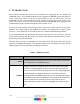
Appendix C Troubleshooting the COM2000 Problem/ Condition Possible Interpretations What to do PWR LED continues to flash for more than 2 minutes after reboot Card is still searching for guide. Communication with card may be unreliable until guide data is acquired. Tuner LED is unlit / SNR = 0 / AGC = -140 Tuner is not locked to a channel. Card rebooted with “Persistent” field Attempt to retune to the channel. set to ‘0’. Make sure “Persistent” field is set to ‘1’. Possible RF problems.
Problem/ Condition Card required authorization “hits” Possible Interpretations What to do Wait the full 24 hours recommended for Possibly nothing – it could just be a authorization. function of the way the authorization Run through the guide acquisition spotmultiple queue works checks. If all tests pass, tune to channel Possible RF problems 100 and attempt reauthorization. Possible guide acquisition problems Verify that the account has been set up properly.
Problem/ Condition Possible Interpretations What to do Refer to Section 7 and check for errors in upgrade settings. Firmware bug makes a small A card appears to be “stuck” on number of cards use the wrong IP Look for an address like 169.255.7.xxx in the old revision of firmware. address for software update requests. the TFTP logs. If found, temporarily remap the PC’s IP address to a matching subnet. When attempting to upgrade a full chassis, the last couple of cards do not upgrade.