Technicolor ATSC-8 User’s Guide © 2012 Technicolor.
Introduction This document describes the process and procedures for integrating the ATSC-8 product with the COM1000 digital head-end system. The ATSC-8, available from Technicolor, will allow for the reception of over-the-air broadcasts of digital broadcasts and output of this content over an Internet Protocol (IP) output.
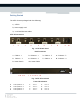
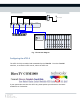
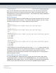
Getting Started The ATSC-8 comes packaged with the following: 1) ATSC-8 2) Power supply cord 3) 4 x 6-foot Ethernet cables ATSC-8 Connections: 1 2 3 4 5 6 7 8 9 Fig. 1 ATSC-8 Back Panel Back Connectors 1. Cable In – 1 2. Ethernet – 1 3. Cable In – 2 4. Ethernet – 2 5. Cable In – 3 6. Ethernet – 3 7. Cable In – 4 8. Ethernet – 4 9. Power Switch 10. Power Cable A B C D 1 2 3 4 5 6 7 8 Fig.
Power/Network LED: Green: The ATSC-8 is powered on and connected to the network. Flashing Green: The ATSC-8 is powered on and working to obtain an IP address from the network. If the PC is connected directly to the ATSC-8, then the light will continue to blink until the PC makes contact with the ATSC-8. Red: Powered on, No Network Link. Tuner LED: Off: The tuner is not in use. Green: The tuner is in use, tuned to a channel, and streaming data.
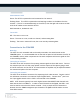
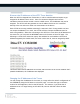
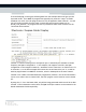
Off Air Antenna 4-way Splitter IP OUT RF IN IP OUT RF IN IP OUT RF IN IP OUT ATSC-8 RF IN Gigabit Ethernet Switch GbE1 Fig. 3 Connection Diagram Configuring the ATSC-8 The ATSC-8 is fully controlled and commanded by the COM1000. From the COM1000 interface, to access the ATSC control, select the ATSC tab. If your system does not show the ATSC tab, please update your software to the latest available from Technicolor. Technicolor MCS 101 W. 103rd St Indianapolis, IN 46290 www.technicolor.
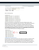
Discover the IP Addresses of the ATSC Tuner Modules When the ATSC-8 is shipped from Technicolor, it will be in DHCP mode and expect to get assigned an IP address from a router. Since our connection diagrams and common installation practices do not include a router or DHCP server, the IP addresses may not be assigned. The ATSC-8 will also generate an Auto-IP address such that a PC connected directly to the unit without a router can communicate to the device.
With the following result: From our previous discovery, we showed both the known IP addresses and the AutoIP addresses for each of the 4 addressable tuners in the ATSC-8. When making the requested IP address change, each device receives 2 commands to change the IP with the second command resulting in the change. In this example, the 4 tuners will have an IP address of 192.168.3.54, 192.168.3.55, 192.168.3.56 and 192.168.3.57. You can verify by again using the DISCOVER button from the ATSC page.
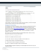
In this example, you’ll see which tuner is tuned to each RF frequency, as well as which QAM IP address and port number each channel has been assigned. Changing the Tuning Table The tuning table can easily be changed by creating or editing the command lines for each of the 8 available tuners. You can verify frequencies and virtual channel numbers in your specific area by using the http://dtv.gov/stationlist.htm website.
Once you have developed a tune table which will work in your area with the appropriate data entered for each of the tuners you need in your system, press the SAVE button, then the RUN button to make this active on the ATSC-8. You should see this change immediately if properly connected to a QAM. QUERY Command The ATSC-8 is able to Query the tuned channels once they have been set up so you can view the signal strength of each frequency.
From the EPG page, entering the following data from the examples above will give you the expected results. Since DIRECTV program data typically only exists for “major” channels broadcast over ATSC, the PSIP program data can only be applied to these channels. You will see in the below example that the minor channels are given program names such as WTHR_Local_Weather. No program data can be provided for these minor channels via the Technicolor PSIP interface. Channel 6.