
User guide


TS 870 TRANSFER SWITCH
PM062 REV 5 08/05/05 3 Thomson Technology
3.2. TRANSFER SWITCHES WITH INTEGRAL OVER CURRENT PROTECTION
For models of transfer switch with integral over current protection, the over current protection
must be set prior to operation. The equipment will be shipped from the factory with a long-
time current setting of 100% (of the equipment rating) and maximum short-
time/instantaneous current and time delay settings.
WARNING!
Do Not Energize this equipment until
device settings have been verified to
ensure proper system protection &
coordination. Failure to do so may
result in equipment failure.
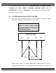
Refer to Section 5.2.2 of this manual for additional information on operation of the Transfer
switch following an over current trip condition.
Refer to information supplied with the transfer switch documentation package for adjustment
procedures on the power switching units over current protection trip unit. Contact the factory
if any additional information is required.
3.3. TRANSFER SWITCHES WITH MULTI-TAP VOLTAGE CAPABILITY
If the transfer switch has programmable multi-tap voltage capability (i.e. ATS Model Code
with Voltage Code “Y”), confirm the transfer switch has been configured for the correct
system voltage prior to installation.
WARNING!
Failure to confirm and match transfer
switch voltage with the system voltage
could cause serious equipment damage.
The voltage selections and connections are shown on the engineered drawings attached to
each transfer switch. The factory default settings will be indicated on the calibration label
attached on the inside of the enclosure door (supplied loose on open style models). A blank
label is included to record the applicable settings if the configuration is changed from the
factory default settings.