
User guide


APPENDIX “A”
THOMSON TECHNOLOGY
©
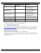
TYPICAL AUTOMATIC TRANSFER SWITCH
COMMISSIONING PROCEDURES Model Series TS 870
3) For 240V High Leg Delta systems refer to the ATS instruction manual for correct phasing
required and re-configuring procedures.
CAUTION: FAILURE TO OBTAIN THE CORRECT ATS PHASING WILL RESULT IN
EQUIPMENT MALFUNCTION AND DAMAGE.
4) Confirm cable size is correct for the lugs supplied in the transfer switch (line and load). Confirm
the cables were meggered by the electrical contractor to ensure no cross phase connections or
conduction to ground.
5) Confirm cable lugs are properly torqued. Confirm cable installation; ensure the cables do not
interfere with normal equipment operation or which may cause component damage.
6) Manually operate the transfer mechanism to the appropriate source of supply. Leave the
Isolation Plug disconnected until final Transfer Switch Commissioning is to be completed.
Final Commissioning
1) Verify installation of the Automatic Transfer Switch as per installation manual and verify wiring
(also see the Pre-Commissioning Checks). Confirm phase, neutral and grounding conductors
are installed as per electrical code requirements. Note: Confirm neutral conductors of both
sources are correctly installed and are solidly grounded for 3 phase 4 wire configurations.
2) Check for mechanical damage (shipping or installer).
3) Check for cable interference with mechanical moving parts or the motor brake on 100A-250A
ATS mechanism.
4) Verify correct control wire interconnects to the engine/generator set auto start/stop circuitry.
Ensure the engine controller automatic start circuit does not draw more than 5.0 amps
(resistive) across the TSC 80 Engine Start contact. The TSC80 Engine Start contact is voltage
free and the only voltage measured should result from the engine controllers internal control
logic. Note: The ATS Engine Start contact CLOSES to start the engine and OPENS to stop the
engine.
5) Place the generator engine controller in the "OFF" position and open the generator local circuit
breaker.
6) Ensure the ATS isolation plug is disconnected prior to application of voltage of the supply
sources.
7) Energize the utility supply and the generator supply sources and verify these meet the correct
voltage, phasing and phase rotation for the ATS and system. Once these have been confirmed
to be correct, de-energize both sources before installing the isolation plug.
8) Once the isolation plug is connected, the ATS and system load may be energized with utility
power once the site electrical contractor and or owner (as required) give authorization to
proceed.
9) If Utility power is within nominal limits, the ATS should transfer to the utility source. To
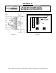
determine correct operation, observe the following on the TSC 80 faceplate:
i) Utility Source green LED is “ON”
ii) Green LED above mimic bus for the Utility source is “ON”