
User guide


TS 870 TRANSFER SWITCH
PM062 REV 5 08/05/05 17 Thomson Technology
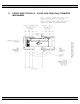
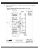
8. TRANSFER SWITCH MECHANISM – 100A-800A, S Style
The transfer mechanism consists primarily of the transfer gear motor, a drive hub assembly, and
two power switching device operating arms.
The reversible transfer gear motor drives the drive hub assembly, which in turn moves the power
switching device operating arms. The power switching device toggles are set inside the operating
arm slots and are moved by them. There are two limit switches, which are contacted by the
operating arms (one for each power switching device), which disconnect the transfer motor power
supply when the power switching devices have attained full travel. Should limit switch adjustment
be required, it is advisable to consult Thomson Technology for further information.
The transfer switch mechanism has three possible positions:
a) Utility power switching device closed and generator power switching device open;
b) Generator power switching device closed and utility power switching device open;
c) Both utility and generator power switching devices open, but NEVER both utility and
generator power switching devices closed at the same time.
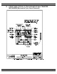
8.1. MANUAL OPERATION
DANGER!!!!
Arc Flash and Shock Hazard. Will cause severe injury or death.
Do not open equipment until ALL power sources are disconnected
This equipment must be installed and serviced only by qualified electrical
personnel utilizing safe work practices and appropriate Personal Protective
Equipment (PPE). Failure to do so may cause personal injury or death
Isolate the transfer switch from all sources of supply before opening the enclosure for
manual operation. With all sources of power de-energized to the transfer switch, the control
circuit isolation plug can be unplugged to prevent subsequent operation. The control circuit
isolation plug is located on the inner side of the transfer switch enclosure door.
To operate manually, insert the operating handle into the square hole on the front of the
mechanism and rotate to the desired position. Remove the operating handle once operation
is complete and re-insert into the handle holder on the left-hand side of the transfer switch
mechanism.