Important safety instructions WARNINGS & PRECAUTIONS Ensure that your domestic mains supply voltage matches the voltage indicated on the identification label located at the back of the set. The monitor components are sensitive to heat. The maximum ambient temperature should not exceed 35o Celsius. Do not cover the vents at the back of the monitor. Leave sufficient space around it to allow adequate ventilation. Install the monitor away from any source of dust or heat (radiator, etc.).
Important safety instructions Installation Install the monitor in a properly ventilated room. Do not install this product on an unstable cart, stand or table. Do not place it on a bed, sofa, rug, or other similar surfaces. Do not install the monitor in an enclosed area unless proper ventilation is provided. Do not rest objects on the power cord and avoid placing power cord near high traffic areas. Do not overload wall outlets and extension cords as this can result in a risk of fire or electric shock.
Table of contents Package contents ............................................................................................................ 4 Understanding your monitor .............................................................................................. 5 Front view ....................................................................................................... 5 Rear view........................................................................................................
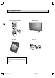
Package contents Remote control with batteries Plasma monitor EN 4 SIZE AAA 1,5 V 0%MERCURY EXTRA HEAVY DUTY GREENE LL + - - + GR EE EX TR NE AH EA SIZ VY LL E AA A 1,5 DU V TY 0%ME RCUR Y User manual Man Bed ien Man uale Use r Man man anle itun tion g ione ual ual de utili zaci 42W uel d’ut ilisa ungs di utili zzaz Power cord ón M 0 2S Optional accessory You can purchase from your local sales representative an optional wall mount under the following reference: Wall moun
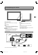
Understanding your monitor Front view EN 5 Power (standby) button Use this button to turn the monitor on from standby mode. Status indicator Off When the monitor is connected to the mains, the main power switch on the rear panel is on the OFF position, the indicator is off. Orange When the monitor is connected to the mains and the main power switch is on the ON position, but the power button on the front panel is off, the indicator is orange. Green When the set is on, the indicator is green.
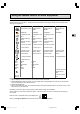
Remote control Most of your plasma monitor functions are available via the menus that appear on the screen. The remote control supplied with your set can be used to navigate through the menus and to configure all the general settings. (red) To access the sleep timer. Inactive EN 6 (green) Inactive To enable the PIP function. Inactive To swap the main picture with the PIP picture. To change position of the PIP on screen. To change channels within the PIP function. (yellow) To access status information.
Using the remote control for other equipment The remote control supplied with your set can be used for other equipment, such as videorecorders, DVD players, satellite receivers or hi-fi systems. This page provides information concerning the remote control’s use with these other types of equipment.
Switching on Follow the instructions on this page to switch on the TV set and the remote control. 1 -+ 2 + 1 Install two LR06 or AA batteries in the remote control. Precautions on using batteries: – Only use the battery types specified. – Make sure you use the correct polarity. – Do not mix new and used batteries. – Do not use rechargeable batteries. – Do not expose batteries to excessive heat, throw them on the fire, recharge them or try to open them, as this could cause them to leak or explode.
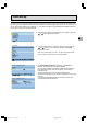
Initial set-up The initial set-up involves setting all the parameters required to be able to search and store all the channels you can receive in your area. Make sure that the TV set is switched on and follow steps 1 to 4. When you first switch the TV set on, the language selection menu appears (1). If this does not happen, refer to the Manual installation section to find out how to carry out an automatic search. 1 Choose which language you want the menus to appear in using the or button.
Initial set-up 4 Organising channels At the end of the auto installation process, the ORGANIZER menu appears to allow you to modify the order of channels, to name or rename channels, or delete channels stored twice or with poor reception quality. Use a TV programme magazine and the channel logos to identify the various channels. Note: The ORGANIZER menu is also accessible from the INSTALLATION menu. If you do not want to reorganise the channels, press exit to close the menu.
Manual installation MANUAL INSTALLATION Return Standard Frequency Name Fine-tuning Store on PR: Decoder Text EURO 150.75 MHz BBC2 02 1 You may want to make a manual installation, in case, some channels have not been stored during the initial set-up. Setting up channels manually requires every setting to be entered, one at a time. To carry out a manual installation, display the OVERVIEW menu using the menu button and select the Installation option. Press ok to confirm.
General operation Switching the set on and off To switch the TV set on, put the main power switch located at the rear on the ON position, then press the power button located on the front panel. When the set is on, the indicator on the front is green. Standby mode: press the power button on the front panel. When the TV set is in standby mode, the indicator on the front is orange. Volume EN Volume control: use the buttons on the front panel or the remote control to increase and decrease the volume.
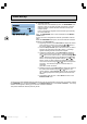
Adjusting the picture Display the OVERVIEW menu using the menu button. Select Picture and press ok to confirm. The PICTURE menu appears. The contents of this menu depends on the signal. Picture menu in TV mode In TV mode: Adjust the Brightness, Contrast, Colour and Sharpness settings as required. The Tint option is only available when a NTSC signal is detected. It is used for adjusting the picture’s tint. To adjust the colour temperature, select the Tone option and select a setting using the and buttons.
Adjusting the sound Display the OVERVIEW menu using the menu button. Select Sound and press ok to confirm. The SOUND menu appears, which offers the following settings: The Sound type option allows to select the relevant sound type. Use the and buttons to make a selection. The available options depend on the programme you are watching. EN 14 Sound Return Sound type Bass Treble Balance Intern.
Picture in picture (PIP) The PIP area on the remote control is used for the PIP functions. These functions allow to view two programmes (one TV channel and one AV programme, or two AV programmes) at the same time in various ways. Press the PIP button to scroll the various display modes: PIP: a TV channel or AV programme is displayed in a frame in a corner of the screen. PAP: the screen is divided vertically in two and the second programme is displayed on the right side.
Other functions Sleep timer This function allows you to set an automatic shut-off time, from 0 to 4 hours, with 15-minute steps. Press the red button on the remote control to activate the sleep timer function. 3 : 45 EN 16 -: -- A symbol appears on screen in front of the sleep time. If no timer has been set, then -:-- is displayed. Use the to decrease/increase the duration. / buttons Once the timer is set, pressing the red button displays the remaining time before shut-off.
Using the Teletext The Teletext service is available in many countries under a variety of names (TOP Text, Fastext, FLOF test, Videotext). It is provided as a free service by some television broadcasters. This service provides a real wealth of information, available at any time, on weather, sporting results, news, games, etc.
Using the Teletext Subtitles Some channels provide subtitles for some of their programmes through Teletext. The numbers of the relevant pages are specified on the Teletext index page. To display the subtitles, enter the number of the relevant page. Once it is found, the subtitles appear in the TV picture. The header and the navigation bar disappear after a couple of seconds. To display them again, press any button (except exit, the button or the volume adjustment buttons) on the remote control.
Connecting other equipment Connecting a DVD player Using SCART (AV) socket input 1. Connect the SCART socket on the DVD player to the SCART socket on the rear panel of the set. EN 19 Using component video input 1. Connect the green (Y), red (PR/CR), and blue (PB/CB) cinch sockets on the DVD player to the corresponding cinch sockets on the rear panel of the set. 2.
Connecting other equipment Connecting a videorecorder Using SCART (AV) socket input This connection gives the best picture and sound quality. 1. Connect the SCART socket on the videorecorder to the SCART socket on the rear panel of the set. 2. Connect the videorecorder to the antenna wall socket or cable box. Using S-video input 1. Connect the S-video (4-pin DIN) socket on the videorecorder to the “S-VIDEO” socket on the rear panel of the set. 2.
Connecting other equipment Connecting external amplified speakers Connect the red (R) and white (L) audio out sockets located to the right of the connector panel of the set respectively to the right and left amplified speakers. EN 21 Connecting an amplifier Connect the red (R) and white (L) audio out sockets located to the right of the connector panel to the amplifier’s L and R inputs. Note: The AUDIO OUT cinch sockets can be set to either Fixed or Variable audio output levels.
Connecting other equipment Connecting a PC Using RGB input 1. Connect the 15-pin RGB connector on the PC to the RGB IN connector located at the rear of the set. 2. Connect the audio sockets on the PC to the R and L cinch audio in DVI/RGB sockets on the rear panel of the set. Using DVI input 1. If your PC is equipped with a DVI (Digital Visual Interface), connect its DVI connector to the DVI IN connector located on the rear panel of the set. 2.
Signal frequency information In PC mode, you can press the yellow info button to access the display mode of the monitor. M. xx appears on screen. Please refer to the table below to get detailed information about the various display modes. Mode Horizontal 1 31.469 2 37.861 3 37.500 4 43.269 5 35.156 6 37.879 7 48.077 8 46.875 9 53.674 10 48.364 11 56.476 12 60.023 13 68.677 14 63.981 15* 79.976 16* 91.146 18 31.469 19 31.469 20* 45.000 21* 33.750 22 31.469 23 31.413 24 35.000 25 49.725 26 68.681 VGA M.
Troubleshooting The following table lists possible problems and methods for remedy. Please refer to this table prior to contacting a service representative. Possible Cause Symptom No picture is displayed. 1. The power cord is disconnected. 2. The main power switch on the rear panel is on the OFF position. 3. The selected input has no connection. 4. The monitor is in standby mode in RGB mode. 1. Plug in the power cord. 2. Put the main power switch on the ON position. 3.
Specifications Display Panel Screen size Aspect ratio Resolution Pixel pitch Luminance 42 inches 16:9 wide 852 x 480 1.08 mm x 1.08 mm 1000 cd/m2 Power Source Input voltage Input current Inrush current Power consumption Standby & Power Save 100 ~ 240 Vac , 50 / 60 Hz 4.5 A 60 A p-p/20 ms max.
Specifications Pin assignments for D-SUB connector (in / loop out) Pin Signal Assignment Pin Signal Assignment Pin Signal Assignment 1 RED 6 RED GND 11 GND 2 GREEN 7 GREEN GND 12 SDA 3 BLUE 8 BLUE GND 13 H-SYNC 4 GND 9 NC 14 V-SYNC 5 GND 10 GND 15 SCL EN 26 Pin assignments for 24-pin DVI connector (digital only) Pin Signal Assignment Pin Signal Assignment 1 TMDS Data 29 TMDS Data 12 TMDS Data 2+ 10 TMDS Data 1+ 3 TMDS Data 2/4 Shield 11 TMDS Data 1/3 Shield 4 TMDS Data 412 TMDS Data 35 TMDS Data 4+ 13 TMDS
Specifications RGB/DVI for Apple standard Refresh Mode Rate No. Resolution (Hz) 24 640 × 480 67 25 832 x 624 75 26 1152 x 870 75 Y/PB/PR for Component Mode Resolution 1 640 × 480p 2 1920 ×1080i 3 1280 × 720p 4 720 × 576p 5 1920 ×1080i 6 1280 × 720p Horizontal Resolution (kHz) 35.000 49.725 68.681 Vertical Resolution (Hz) 66.667 74.550 75.062 V-Sync Polarity (TTL) - H-Sync Polarity (TTL) - Dot rate (MHz) 30.240 57.283 100.
Specifications Reliability Requirement The MTBF is 20,000 hrs under operation 25 ± 5o C (Half luminosity, motion picture) Emission Requirement The product meets the EMI limits in all screen modes as qualified by FCC class B part 15.
Specifications Preset Timing Chart EN 29 Item A B C D E F G H I Description: Total time Active display area including borders Active display area excluding borders Left/Top border Right/bottom border Blanking time Front porch Sync-width Back porch Mode No H Resolution V Resolution Refresh Rate Pixel Horizontal visible Horizontal total Horizontal front porch Horizontal sync Horizontal back porch Horiz blanking time Vertical visible Vertical total Vertical front porch Vertical sync Vertical back porch Ver
Specifications EN 30 Mode No H Resolution V Resolution Refresh Rate Pixel Horizontal visible Horizontal total Horizontal front porch Horizontal sync Horizontal back porch Horiz blanking time Vertical visible Vertical total Vertical front porch Vertical sync Vertical back porch Vertical blanking time Horizontal frequency Vertical frequency Vertical sync polarity Horiz sync polarity 10 1024 768 60 65.000 1024 1344 24 136 160 320 768 806 3 6 29 38 48.364 60.004 - 11 1024 768 70 75.
Wall mount installation (optional) Package Content An optional wall mount (ACC 913) is available. Contact your local retailer for more information. Right module Left module Horizontal supports C D A B Screws for assembling wall mount (8) E 42WM03STW-0707-en.
Wall mount installation (optional) Installation steps Step 1. Attach the horizontal supports (C and D) to the left and right modules ( A and B) using the appropriate screws (E). EN 32 Step 2. Install the wall mount bracket onto the wall. Note: This package includes two different sets of screws - one for mounting on a cement wall and one for a wooden wall. Please consult with a qualified installer to make sure that this wall mount and plasma monitor can be installed.
Wall mount installation (optional) Step 3. Remove the table-top stand, install the monitor onto the wall mount bracket. EN 33 Note: This wall mount is an optional accessory, please contact your local sales agent for more information. This type of equipment is to be installed by qualified installers, please contact with authorized dealer for installation. Please make sure that the wall can support this wall mount and plasma monitor which can weigh over 120 kg. 42WM03STW-0707-en.