
User's Manual
TM-200 Issue 1.02 November 2005 Page 7 of 64
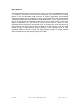
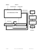
Block Diagram
The baseband input source enters through a Video In connector, and Baseband Audio In
or 4.5 Audio In connector on the back of the modulator. The connectors are mounted
directly on the A/V Modulation PCB where the IF output is generated. The baseband
video signal passes into the modulator, through a group delay filter, and onto the Signal
Conditioning PCB to the video detect/sync level adjust section. The IF signal from the IF
loop on the modulator is connected through the IF pre-correction portion of the same
Signal Conditioning PCB. The visual IF carrier and the aural IF carrier are then
combined before entering the Upconverter PCB. The outputs are at RF frequencies of
945.75 MHz for the visual carrier and 941.25 MHz for the aural carrier. Then, the signal
passes through a Downconverter section allowing a user selectable VHF or UHF
broadcast television channel. Finally, the signal passes through an output amplifier
which increases the RF signal level typically to 15 dBm.