
User's Manual


TM-200 Issue 1.02 November 2005 Page 28 of 64
6.0
P
ROBLEM
T
ROUBLESHOOTING
G
UIDE
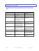
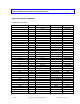
The guide below covers some typical symptoms, possible associated causes and
suggested actions to follow before returning the unit for repair. It is not meant to be all-
inclusive.
Symptom Possible Cause Suggested Action
No output or weak output Baseband input level too weak Ensure proper 1 Vp-p video signal
present on input
IF loop cable on rear of unit loose
or disconnected
Check IF loop cable is securely
attached
Unit not plugged in or getting AC
power
Check power cord and power source,
fuse
Unit tuned to output channel
different from desired (this occurs
particularly on the units which
have green LED on the front
panel to indicate “T” channels and
channels above 99)
Ensure selected output channel is
desired channel
Loss of video on the input – video
detect turned off RF Output
Ensure proper 1 Vp-p video signal
present on input
Excessive noise or spurious
signals
Output level above rated
maximum (most often occurs
when changing from high-number
channel to low-number channel,
especially to the “T” channels)
Measure RF output from rear
panel jack and adjust front panel
OUTPUT LEVEL control as
required
IF level too high (most often
occurs when routing IF through
scrambler or other external
device)
Measure normal IF output level
for applied CW/unmodulated input
carrier and ensure same level is
returned to unit after external
processing
Input signal too strong or no input
signal at all
Measure video level and pad to
within specified input levels.
Bad/noisy video Aural carrier interfering with video
carrier
Measure Aural Carrier level
and/or adjust AURAL CARRIER
LEVEL control on front panel
Channels do not change Delay feature active Hold channel change switch in
raised/lowered position for at least
three seconds