
User's Manual

TM-200 Issue 1.02 November 2005 Page 22 of 64
Setup of Baseband Audio Input Connection and Adjustment
1. If your Technalogix TM-200 agile modulator is equipped with a 4.5MHz sub-
carrier input option, ensure that the rear-panel AUDIO SELECT switch is in the
BASEBAND position.
2. Connect a 1V
P-P
baseband audio signal to the rear panel baseband audio
connector as follows:
• For balanced input connection, connect one audio input lead to the
left terminal on the connector and the other audio input lead to the
right terminal.
• For unbalanced input connection, connect one audio input lead to the
left terminal on the connector and the other audio input lead to the
center terminal.
• Center terminal is chassis ground.
• Insert the terminal into the connector on the rear panel of the TM-200.
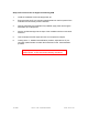
3. Adjust the front panel AUDIO MODULATION control for 100% modulation.
• Set the front panel DISPLAY SELECT switch to AUDIO (up) position.
• Observe front panel LED bar graph behind front panel display readout
window.
• First RED LED will begin illumination at approximately 95%
modulation; or
• Adjust for ±25KHz deviation using a spectrum analyzer; or
• Listen to the audio output from TV monitor and setting the loudness
equal to that of an off-air channel carried on your system.