
User's Manual
TM-200 Issue 1.02 November 2005 Page 11 of 64
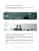
Signal Conditioning Module
The TM-200 modulator includes a separate circuit board called the Signal Conditioning
Module. The Signal Conditioning PCB contains the video detect/sync level adjust
section in addition to the IF pre-correction section. The baseband video signal passes
into the modulator, through a group delay filter, and onto the Signal Conditioning PCB to
the video detect/sync level adjust section. The IF signal from the IF loop on the
modulator are connected through the IF pre-correction portion of the same PCB. The
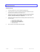
Signal Conditioning features are as follows:
1. Sync Level Adjust - Allows the user to adjust the sync level to maintain the
proper level. Adjustment is made via front panel.
2. Video Detect - Turns off the 24Vdc supply to the final amplifier stage in the TM-
200 in the event of missing video input. The power supply for the final amplifier
(+24Vdc) is routed through a relay on the Signal Conditioning PCB. In the event
of a missing video signal, the relay contact is opened and the +24Vdc is
disconnected from the final amplifier stage.
3. IF Pre-Correction – Allows the user to optimize the linearity of their power
amplifier using slope-knee adjustments available from front panel. Adjustment
will alter several RF performance parameters including in-band intermodulation
products, differential phase and gain, and others.
The input and output impedance of the Signal Conditioning PCB is 75-ohms. Baseband
video connections are made via RCA connectors for the sync level adjust and video
detect sections and the IF connections are made via F connectors. The Signal
Conditioning PCB can be bypassed, if necessary.