
User Manual

Technalogix Ltd. TM-100 Modulator
16
3. Observe the output on the spectrum analyzer, or the field strength meter.
If measuring from the rear panel RF OUTPUT jack, adjust the front panel
OUTPUT LEVEL potentiometer for an output level between +55dBmV and
+60dBmV. If measuring from the front panel –20dB TEST POINT, ensure
that the rear panel RF OUTPUT jack is terminated into a 50Ω load, then
adjust the front panel OUTPUT LEVEL potentiometer for an output level
between +35dBmV and +40dBmV.
4. If using a field strength meter, retune the meter to the frequency of the
audio RF Carrier.
5. Still observing the output on the spectrum analyzer, or the field strength
meter (now tuned to the frequency of the audio RF carrier), adjust the front
panel AURAL CARRIER potentiometer for an output level 10-13dB lower
than that at which the video RF Carrier is set.
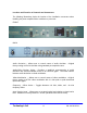
6. Remove the spectrum analyzer, or field strength meter from the unit. If
available, connect a television/monitor to the front panel –20dB TEST
POINT, apply power to the television/monitor and tune to the selected
output channel of the Technalogix TM-100 modulator.
B. VIDEO input connection and adjustment.
1. Connect a 1.0V
P-P
video source to the VIDEO IN jack on the rear panel.
2. Adjust the front panel VIDEO MODULATION control for 87.5%
modulation.
• Set the front panel DISPLAY SELECT switch to VIDEO (down)
position;
• Observe front panel LED bargraph behind front panel display
readout window.
• First RED LED will begin illumination at approximately 87.5%
modulation; or
• Observe TV monitor for good visual image.