
User Manual

Technalogix Ltd. TM-100 Modulator
15
5.0 OPERATING PROCEDURE
Preliminary Hook-up
1. Terminate modulator into a 50 ohm load before applying power.
2. Connect the power cord of the Technalogix TM-100 agile modulator to a
proper electrical source as indicated on the back of the unit
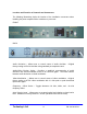
3. Observe the front panel. If power is applied and present, the red power
LED will illuminate. Also, all the elements of the displays behind the
display readout window will illuminate momentarily as a display test.
4. Observe the numbers displayed behind the display readout window after
the test. They will indicate:
• Microprocessor software version;
• Internal option dipswitch settings;
• RS-232 unit ID (if so equipped); and
• Last tuned channel.
5. After a moment, the Lock Detect LED will illuminate.
Setup and Operation
A. Output level and channel selection; connecting monitor.
1. Connect a spectrum analyzer, or a field strength meter tuned to the
frequency of the video RF carrier of the desired channel, to the RF
OUTPUT jack on the rear panel of the unit. Alternatively, connect a
spectrum analyzer or a field strength meter to the –20dB TEST POINT on
the front panel of the unit.
2. Select the desired output channel using the CHANNEL SELECT paddle
switch on the front panel.
• Hold the CHANNEL SELECT switch in the up- or down-position
for approximately 3 seconds to activate the channel-select
circuit;
• Toggle the CHANNEL SELECT switch up to select a higher
channel or toggle it down to select a lower channel. The switch
may be held in the up- or down-position for rapid channel
switching.