
User Manual

Technalogix Ltd. TM-100 Modulator
14
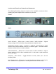
Output Select – Selects the desired channel of operation. If you require a lower
channel than the one currently displayed, push the toggle switch down. The
channels will change one at a time as many times as you press the switch.
Holding the select switch in the up or down position will “scan” to the desired
channel. It is normal for the frequency lock LED to turn off during and for a few
seconds after, changing channels. The switch must be held up or down initially
for three seconds. This helps to ensure that no accidental channel changes will
occur.
Output Level – Sets visual carrier output level.
RF Out Test Point – Provides a sample of the RF output level which is 20 dB
below the actual value. RF test point is only a relative indicator of the actual RF
output level and may vary. All RF operating measurements should be made at
the RF output of the unit.
RF Output - Modulated Audio/ Video output capable of +60 dBmV levels using
built in low distortion hybrid amplifiers.
RS-232 Ports – Set up for optional RS-232 control option.
Combined IF Input/ Output – 45.75 MHz visual carrier and 41.25 MHz audio
carrier intermediate frequency signal loop.
Audio Input/ Ouput Loop – Available for baseband audio processing.
Video Input/ Output Loop - Available for baseband video processing.
Video In – Connection for 1.0 Volt peak to peak video source.
Balanced Baseband Audio In – Used to connect a 1 Volt peak to peak baseband
audio signal. For balanced input connection, connect 1 audio input lead to the
left terminal on the connector and the other audio input lead to the right terminal.
For an unbalanced input connection, connect one audio input lead to the left
terminal on the connector and the other audio input lead to the centre terminal.
Center terminal is chassis ground.