
User's Manual

IV-4
Splitter/Combiner
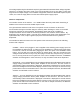
The splitter and combiner (identical printed circuit boards) are used to split the RF signal into, and combine the
amplified RF signal out of the (2) final amplifier pallets. The microstrip designs are based on the simple isolated
Wilkinson combiner design. Flanged power resistors help ensure that any differences between the inputs or
outputs is balanced. Due to its electrical and mechanical symmetry, the Wilkinson design’s performance over
moderate bandwidths is superior to other types.
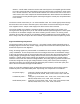
Directional Coupler
The Technalogix dual directional couplers provide DC voltages proportional to forward and reflected RF power
monitoring. These analog voltages are converted for processing using analog-to-digital converters and provide the
control system with valuable data for monitoring purposes. The directional couplers installed in the power
amplifier and filter enclosures have peak detection circuits on the forward RF power side of the coupler and
average detection circuits on the reflected RF power side of the coupler. This is to allow the end user to set
power in a manner that is more independent of modulation and closer to a true tip-of-sync meter. Hence the
readings on the displays in the power amplifier system are peak for forward and average for reflected. Output
power should be set following the operating procedure found elsewhere in this manual.
The directional coupler has a typical insertion loss of 0.5dB and its Type N connectors can handle 1,500 watts
peak. The coupler requires 5 Vdc to power the internal electronics of the coupler and is supplied from the control
printed circuit board at the front of the enclosure.
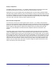
Filter
The passive bandpass filter rejects spurious and harmonic output products and passes the VHF channel RF
output. The cavity resonator uses aperture coupling and is a linear resonator design. Typical insertion loss is 0.6
dB to 1.0 dB depending on channel frequency. Average roll off is –33 dBc at a point 4.5 MHz below the peak
visual carrier frequency and –30 dBc 9.0 MHz above the peak visual carrier frequency. The filter is DC grounded
on both the input and output for additional lightning protection.