
User's Manual

VI-4
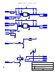
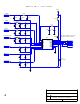
Display Components
The display section of the Series II – rev I PCB is comprised of the LCD and the components that
make up the data bus to send the data from the microcontroller to the LCD.
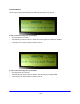
Specifically, the LCD is an alphanumeric 20X4 display that uses the industry standard 44780
controller and a parallel interface for data communications. Firstly, the microcontroller sends out
the data to be displayed via a serial bus where the signals are latched with U111 and U112 and
converted to a parallel data stream. The parallel data then transfers directly to the LCD through
connector J109. J109 also carriers the power supply for the LCD.
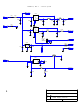
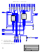
Microcontroller Components
The heart of the monitor and control system found in Series II - rev I PCBs is microcontroller U114.
This microcontroller analyzes all RF power levels and voltages to ensure that all operating
parameters are within their predetermined safe operating levels. If a fault is found, appropriate
action is taken to help protect the system from damage, which may include turning the RF carriers
off. A full description of all faults and their respective actions is found later in this section.
The power supply for the microcontroller is monitored closely via supervisor U113. Should the
+5Vdc supply drop below +4.5Vdc, a microcontroller reset is generated to ensure there are no
brown out conditions that may latch the microcontroller up to an unknown state. The front panel
Reset momentary switch is also tied to this line after optoisolation. The microcontroller is run off of
a 4.000MHz clock source, generated by ceramic resonator CR101. If the software is running, LED
D110 will be lit. Finally, U115 stores all characters for the LCD to minimize the overhead required
for the microcontroller, and also stores the current state of the power ON/OFF of the system. This
is to ensure that, in the event of a power outage, the system returns to the exact state is was
before power was interrupted.