
User's Manual


IV-5
Final 2-Way Combiner (internal to combiner/filter enclosure)
The RF outputs from the (2) TAU-500 amplifier modules then pass into a final enclosure where the
signals are combined, then filtered and monitored once again. The combiner is a 2-way, 1,000-watt
power combiner with a maximum phase imbalance of +/-1 degree. Minimum isolation is -18 dB and
maximum insertion loss is -0.45 dB from 170 to 280 MHz. Minimum return loss from ports 1 to 2 (input
to input) is -25 dB and -20 dB on port 3 (output).
Directional Coupler (internal to TAU-500 and combiner/filter enclosures)
The Technalogix dual directional couplers provide DC voltages proportional to forward and reflected
RF power monitoring. These analog voltages are converted for processing using a 10-bit analog-to-
digital converter and provide the control system with valuable data for monitoring purposes. The
directional couplers installed in the power amplifier and filter enclosures have peak detection circuits
on the forward RF power side of the coupler and average detection circuits on the reflected RF power
side of the coupler. This is to allow the end user to set power in a manner that is more independent of
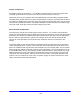
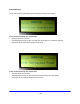
modulation and closer to a true tip-of-sync meter. Hence, the readings on the displays in the power
amplifier system are peak for forward and average for reflected. Output power should be set by the
following procedure:
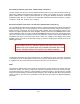
THE POWER OUTPUT SHOULD NEVER BE ADJUSTED EXCEPT
UNDER THE TEST CONDITIONS OF NO AURAL CARRIER, WITH THE
VISUAL CARRIER MODULATED WITH SYNC AND BLANKING.
The directional coupler has a typical insertion loss of 0.05dB and its Type N connectors can handle
1,500 watts peak. The coupler requires 8 to 8.5Vdc to power the internal electronics of the coupler and
is supplied from the control printed circuit board at the front of each enclosure.
Filter
The passive bandpass filter rejects spurious and harmonic output products and passes the UHF
channel RF output. The cavity resonator uses aperture coupling and is a linear resonator design.
Typical insertion loss is 0.6 dB to 1.0 dB depending on channel frequency. Average roll off is –33 dBc
at a point 4.5 MHz below the peak visual carrier frequency and –30 dBc 9.0 MHz above the peak visual
carrier frequency. The filter is DC grounded on both the input and output for additional lightning
protection.