POWER AMPLIFIER NEW ADVENTURES IN BROADCASTING Technalogix TAU-1000
You’ve already unpacked it, haven’t you? You’ve unpacked it and plugged it in and turned it on and fiddled with the knobs. No? Okay, good. Please take a few minutes to read the manual and familiarize yourself with your new Technalogix power amplifier. We believe that this manual, and of course our equipment, should be everything you need to get on the air with superb broadcast quality video.
Table of Contents SECTION I- SAFEGUARDS ..............................................................................................I-1 SAFETY AND FIRST AID.....................................................................................................I-2 OPERATING SAFEGUARDS ................................................................................................I-3 SECTION II - WARRANTY .............................................................................................
SECTION VIII - INSTALLATION.................................................................................. VIII-1 BUILDING RECOMMENDATIONS ................................................................................... VIII-1 HEATING AND COOLING REQUIREMENTS .................................................................... VIII-2 ELECTRICAL SERVICE RECOMMENDATIONS................................................................ VIII-3 ANTENNA AND TOWER RECOMMENDATIONS...............................
Section I - Safeguards General Safeguards This section is written as a general guide to keep all 5 fingers on your hand and is intended for those having previous knowledge and experience with these kinds of equipment. It is not intended to contain a complete statement of all safety precautions, which should be observed by personnel using this or other electronic equipment. DOCUMENTATION - Read, retain and follow instructions before operating the equipment.
Safety and First Aid Personnel engaged in the installation, operation, maintenance, or servicing of electronic equipment are exposed to the hazard of high voltage. It is imperative that all safety regulations and precautions are consistently observed. Knowledge of first aid procedures is recommended. The following information is presented as a reference only. • At all times, avoid placing any part of the body in series between ground and circuit points, whether power is on or off.
Operating Safeguards It is a known fact that our broadcast transmitters and translators enjoy 50-ohm load impedances. So much so, that it is imperative you maintain 50-ohm impedances throughout your system. In return, your equipment will provide you with maximum power transfer to the antenna and decreased reflected power heading back towards the amplifier pallets, reducing the amount of magic smoke that gets let out of the power amplifier.
Section II - Warranty Our legalese is straightforward. It is simply designed to give you peace of mind and helps you resist the temptation to have your electronics friend try to repair your Technalogix product. Technalogix Ltd. products have been completely tested and found to meet specifications and be in proper operating condition. They are warranted to be free from defects in materials and workmanship for a period of one year from the date of shipment.
To claim your rights under this warranty: • Contact Technalogix and describe the problem in as much detail as possible. See troubleshooting section in this manual. If a solution cannot be found at this time, it may be determined that the unit will have to be returned to Technalogix for repair, once a Return Materials Authorization (RMA) number is provided. Please look under our web site (www.technalogix.ca) for the RMA form (Service) and fill it out. Either fax it to us or email to us.
Section III – Overview Standard Features • Narrow output bandpass filter allows adjacent channel operation • Front panel Liquid Crystal Display (LCD) to monitor forward and reflected RF power, and DC voltage • Microcontroller-based monitoring and control ensures amplifier will never be overdriven and high VSWR will not damage amplifier • AC circuit breaker on back panel to eliminate replacement of fuses • All aluminium enclosure maintains power amplifier’s light weight • Simple design using com
Principle of Operation The TAU-1000 power amplifier supplies a 1000-watt peak video signal with 10% aural power on any of the UHF television channels 14 through 69. Please note that channel selection must be made at time of order, as the transmitter or translator is calibrated and tested to the channel requested and is not field tuneable.
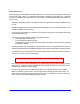
TAU-500 2-WAY SPLITTER COMBINER FILTER RF OUT TO WATTMETER AND ANTENNA MODULATOR/PROCESSOR TAU-500 POWER SUPPLY TAU-1000 Overall Block Diagram Rev ID Date: May 24, 2005 Page: 1 of 1
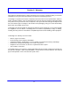
Inside each 500-watt power amplifier, the signal passes through an RF attenuator to limit the output power level of the power amplifier, to help buffer any transients that may come into the power amplifier, and most importantly, allow for provisions to balance the gain of the TAU-500 to the other TAU-500. After attenuation, the signal gets preamplified through a TECH–30U driver amplifier before the signal gets split into (2) signals for final amplification using a 2-way Wilkinson microstrip power divider.
P300-UHF FINAL 2-WAY SPLITTER A=14dB min. 2-WAY COMBINER TECH-30U CIRCULATOR A=-0.5dB typical DIRECTIONAL COUPLER ATTENUATION RF INPUT RF OUT V V i V To Wattmeter and Antenna A=-0.05dB typical A=+38dB min. A=-0.2dB typical A=-0.2dB typical P300-UHF FINAL 50 OHM TERMINATION A=14dB min.
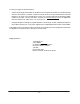
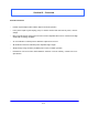
After amplification, the signal exits the power amplifier enclosure and goes into the combiner/filter enclosure, where the signals from each 500-watt amplifier are combined. After combining, the amplified signals are filtered with a bandpass filter and monitored again with another directional coupler before heading out to an antenna for broadcast, as depicted in the following combiner/filter block diagram.
2-WAY COMBINER FILTER DIRECTIONAL COUPLER PA1 OUT RF OUT PA2 OUT V V A=-0.05dB A=-0.45dB typ. TO WATTMETER AND ANTENNA A=-0.6dB typ.
Specifications The following specifications were taken with a Technalogix modulator/processor. Should a different modulator or processor be used, specifications could vary. For this reason, we recommend that any different modulator/processor be shipped to Technalogix so the system can be matched and set up optimally. In addition, the audio/video ratio the input to the power amplifier needs to be –10 dB in order for the software and LCD readout to be accurate.
Aural Characteristics Input Level for 25 kHz Deviation Frequency Response (Standard Pre-emphasis) Harmonic Distortion (25 kHz Deviation) Amplitude Modulation Noise Frequency Modulation Noise Intercarrier Stability 0.3 VPP ±1 dB < 1% 50 Hz to 15 kHz > 50 dB > 60 dB ±250 Hz Physical Characteristics Power Requirements Power Supply Operating Temperature Dimensions TAU-500 Power Amplifier (each) Combiner Power Supply III-8 230 VAC , 28 AAC 0 - 50°C W-19" flange (17” encl.
Section IV – RF Components Amplifier Pallets The TECH-30U driver pallet consists of (2) separate printed circuit board stages – The first stage is an ultra-linear class-A stage with (3) gain sections providing a typical adjustable power gain of 26dB to 37dB at 10-watts peak. This stage typically draws 2.5 Adc quiescent and a maximum drain current of 5 Adc. The second stage is a linear class AB stage with a typical gain of 13 dB. This stage typically draws 1.
P300-UHF-16 Schematic
Power Divider/Combiner (internal to each TAU-500 enclosure) A Wilkinson power divider and combiner are used to split the RF signal into, and combine the amplified RF signal out of the (2) P300 final amplifier pallets. Flanged power resistors help ensure that any differences between the inputs or outputs are balanced.
Final 2-Way Combiner (internal to combiner/filter enclosure) The RF outputs from the (2) TAU-500 amplifier modules then pass into a final enclosure where the signals are combined, then filtered and monitored once again. The combiner is a 2-way, 1,000-watt power combiner with a maximum phase imbalance of +/-1 degree. Minimum isolation is -18 dB and maximum insertion loss is -0.45 dB from 170 to 280 MHz. Minimum return loss from ports 1 to 2 (input to input) is -25 dB and -20 dB on port 3 (output).
Section V – Power Supply Switching AC-DC power supplies are used to power the amplifier pallets, the control circuits, and all of the fans. There are (2) supplies are set at 31.0 Vdc nominally. All fans run off this same supply, though they pass through a series dropping resistor to lower the supply voltage, as the fans are 24Vdc. A 24Vdc nominal power supply is located in the combiner enclosure. It simply supplies power to the control PCB and the cooling fan.
Section VI – Monitor and Control System Control Board Overview (Series II-rev I) The control printed circuit boards (PCB) are located at the front of each enclosure connected directly to the back of the liquid crystal displays (LCD) and are identified as Series II – rev I PCBs. The main purpose of the Series II - rev I PCB is to monitor the RF power and the DC supply voltages in the power amplifier and filter enclosures and to monitor just the DC supply voltages in the power supply enclosure.
The voltage required by the directional coupler is generated with a standard linear voltage regulator, U103 if it is a voltage other than +5Vdc. C107 and C108 helps clean up any ripple or noise that might be on the output voltage. In the standard configuration, where the directional coupler requires +5Vdc, the +5Vdc is simply taken from the U101 filtered power supply output.
RESET – Tactile switch resets the monitor and control system. The amplifier gets shut down for under 0.5 seconds and comes back on with each depress of the reset button. At the same time, all fault counters in the microcontroller software are reset and the LCD is reset in the same manner as it is with a depress of the NAVIGATE button. Reset switches are individual to each enclosure but may be tied together externally through the remote port, as explained later in this section.
Display Components The display section of the Series II – rev I PCB is comprised of the LCD and the components that make up the data bus to send the data from the microcontroller to the LCD. Specifically, the LCD is an alphanumeric 20X4 display that uses the industry standard 44780 controller and a parallel interface for data communications.
Fault Shutdowns On the LCD (Liquid Crystal Display) the following messages may appear: If you see this message, the system will: - shut amp down for 1 minute - automatically turn amp on after 1 minute and check again for overdriven amplifier - come back to the same power level that it was set If you see this message, the system will: - shut amp down for 5 minutes - automatically turn amp on after 5 minutes and check again for high VSWR - come back to the same power level that it was set VI-5
Remote Port The remote port allows external control of the transmission system via the DB25 connector on each enclosure.
Series II - Bill of Materials revision: I date: 21-Jun-05 Item Qty 1 1 Components BZ101 Optional part depending on power level of TV or FM Description Tolerance BUZZER, magnetic, 5V, single tone Package SMD CT-1205C Equivalency CUI CT-1205C 2 2 C101, C105 CAPACITOR, electrolytic, 100uF, 63V <=20% SMT (Panasonic VS "G" size) Panasonic ECE-V1JA101P, NIC NACEW101M63V10x10.
Series II - Bill of Materials revision: I date: 21-Jun-05 40 41 1 1 42 43 44 45 4 1 1 1 R117 R124 R125, R127, R126, R128 R129 R130 R131 46 2 U101, U102 47 2 U101, U102 48 49 50 1 2 1 U104 U105, U106 U108 51 52 1 1 U109 U110 53 2 U111, U112 54 1 U113 55 1 U114 56 57 58 1 1 1 59 4 Optional part depending on power level of TV or FM RESISTOR, 4.99 kohm, 1/10 watt, thick film RESISTOR, 13 kohm, 1/8 watt RESISTOR, 1 kohm, 1/8 watt RESISTOR, 121 kohm, 1/8 watt RES, 2.
SERIES II, REV. I - Control System Vin Cond U101 3 + D101 L101 L102 Vout 2 +5Vdc + 1 Vin 5 On/Off Feedbk 4 F101 3 Gnd J101 Vin C101 C102 D102 C103 C104 J101 GND 4 U102 L103 R101 Vout 1 Pin15LCD + 3 Gnd + C105 5 On/Off Feedbk 4 2 Vin C106 D103 BK LT J102 CTRL SELECT BkLtCtrl U103 IN J101 Vcoupler OUT 1 COM C107 C108 J101 GND +5Vdc 2 VR101 U104 P8 P7 P6 P5 P1 P2 P3 P4 + +5Vdc C109 R102 + Pin3LCD 1 C110 R103 A.
SERIES II, REV. I - Control System +5Vdc R104 PWR In J103 R105 R106 1 R107 R108 U105 J104 1 P1 P2 P3 P4 P8 P7 P6 P5 VW uPC PWR uPC VW In J103 2 R109 NAV In J104 +5Vdc 2 R110 R111 +5Vdc R112 R113 NC(RC6) SEL In R114 J103 4 U106 J104 4 P1 P2 P3 P4 P8 P7 P6 P5 PIN17uPC RES uPC RES In J103 3 R115 +5Vdc J104 5 Ground J103 5 J104 3 BZ101 +5Vdc J105 Buzzer R116 Buzzer delete Q101 +5Vdc J106 +5Vdc J107 Rly. COM 2 J107 K101 D104 Rly. N/O 3 J107 Rly. N/C R117 Rly.
SERIES II, REV.
SERIES II, REV.
5 4 U11: LCD control signals, LCD backlight control, and External interface outputs U12: LCD data bus (D0...D7) D0...D7 is text or instruction 3 14 2 13 U112 serial_out GND reset Qh(out_7) shift_clk Qg(out_7) latch_clk Qf(out_6) output_en Qe(out_5) serial_in Qd(out_4) Qa(out_1) Qc(out_3) Vcc Qb(out_2) 6 Ext.
SERIES II, REV. I - Control System Vcc U113 Reset Reset GND Vcc +5Vdc C144 C145 U114 Dclk DfromUPC DtoUPC Latch1CS Latch2CS Buzzer CR101 GND OSC1 OSC2 CONVST MCLR/Vpp RB7 RA0 RB6 RA1 RB5 RA2 RB4 RA3 RB3 RA4 RB2 RA5 RB1 Vss RB0/INT OSC1/CLKin Vdd OSC2/CLKout Vss RC0/T1CKI RC7/RX/CK RC1/CCP2 RC6/TX/CK RC2/CCP1 RC5/SD0 RC3/SCK/CL RC4/SDI/SDA Dig.Out1 Dig.Out2 Rly.Ctrl Dig.In 3 Dig.In 2 Dig.In 1 D110 R134 U115 Vcc *HOLD SCK SI + *CS SO *WP Vss C146 C147 A.
J3<3> RES J3<1> PWR J3<4> RC6 J7<2> DIS Grey 22AWG J3<3> RES Brown 22AWG J3<1> PWR J7<2> DIS Grey 22AWG Brown 22AWG Purple 22AWG J1 5 4 3 2 1 Red 22AWG + Red 22AWG DRIVER DISABLE PAD V+ PSU White 22AWG Purple 22AWG Green 22AWG Power Amplifiers DB9 PA1 CTRL DB25 REMOTE PORT 1 2 3 4 5 6 7 8 9 1 2 3 4 5 6 7 8 9 10 11 12 13 14 15 16 17 18 19 20 21 22 23 24 25 DB9 CTRL 1 2 3 4 5 1 2 3 4 5 6 7 8 9 DB25 REMOTE PORT 6 7 8 9 1 2 3 4 5 6 7 8 9 10 11 12 13 Green 22AWG 14 15 16 17 18 19 20
Section VII – Mechanical Section The heat sink allows the amplifiers to operate at a cooler temperature and prevents overheating, which helps the longevity of the entire system. The heat sink has hollow fins, which help dissipate the heat from the amplifiers faster than a conventional serrated or corrugated fin.
Section VIII - Installation This section contains installation recommendations, unpacking, inspection, and installation instructions for the power amplifier. We are sure that you are chomping at the bit to install your new system, so we recommend that you read the following sections very carefully. Building Recommendations The quality of the building is of great importance if you are to expect long life and continued performance from the power amplifier.
Heating and Cooling Requirements The environment’s temperature will contribute greatly to the length of the power amplifier’s life. Technalogix recommends that the building’s filtered air intake must have capacity for all air-flow in the building plus an additional 20%. Keep the intake below the roofline to avoid intake of solar heated air. Please ensure that the intake and exhaust areas are on the same side of the building to avoid pressure differentials during windy conditions.
Electrical Service Recommendations Technalogix recommends that a qualified, licensed local electrician be consulted for the required electrical service. We suggest local electricians because: • The personnel knows the local codes • The personnel can be on site readily • You are apt to get better overall support if you give what business you can to local suppliers Technalogix recommends that proper AC line conditioning and surge suppression be provided on the primary AC input to the power amplifier.
Antenna and Tower Recommendations Your preliminary engineering workgroup should establish your antenna and tower requirements, both for receiving and transmitting antennas. Construction of sturdy, high quality antenna/tower systems will pay off in terms of coverage of your service area, the overall quality and saleability of your radiated signal, and reduced maintenance expenses. Technalogix provides complete turnkey antenna systems if needed.
Shelter Security The FCC requires that the transmitter or translator be secure from entry or control by unauthorized persons, and that any hazardous voltages or other dangers (including most tower bases) be protected by locks or fences as necessary to protect personnel and prevent unauthorized tampering or operation. Security of the building further implies that it be secure from wildlife. Use sturdy construction materials, including sheet metal if necessary.
Unpacking and Inspection Check the outside of the container. Carefully open the container and remove the power amplifier. Retain all packing material that can be reassembled in the event that the equipment must be returned to the factory. Exercise care in handling equipment during inspection to prevent damage due to rough or careless handling. Visually inspect the enclosure of the power amplifier for damage that may have occurred during shipment.
Location and Function of Controls and Connectors (TAU-500 Power Amplifier) The following illustration depicts the location of the connectors when installing each of the 500-watt power amplifiers (TAU-500). Technalogix Ltd.
POWER - Tactile button to turn carriers on and off. To turn off, must be depressed for at least 2 seconds. Tied internally through DB9 connectors to all other POWER buttons. NAVIGATE - Tactile button to refresh screen after two minute screen saver times out. All monitoring and protection continues during screen saver. SELECT- Tactile button to refresh screen after two minute screen saver times out. All monitoring and protection continues during screen saver.
Location and Function of Controls and Connectors (Power Supply) The following illustration depicts the location of the connectors when installing the power supply. Technalogix Ltd.
POWER - Tactile button to turn carriers on and off. To turn off, must be depressed for at least 2 seconds. Tied internally through DB9 connectors to all other POWER buttons. NAVIGATE - Tactile button to refresh screen after two minute screen saver times out. All monitoring and protection continues during screen saver. SELECT- Tactile button to refresh screen after two minute screen saver times out. All monitoring and protection continues during screen saver.
Location and Function of Controls and Connectors (Combiner/Filter) Technalogix Ltd.
POWER - Tactile button to turn carriers on and off. To turn off, must be depressed for at least 2 seconds. Tied internally through DB9 connectors to all other POWER buttons. NAVIGATE - Tactile button to refresh screen after two minute screen saver times out. All monitoring and protection continues during screen saver. SELECT- Tactile button to refresh screen after two minute screen saver times out. All monitoring and protection continues during screen saver.
Initial Hook Up 1. Ensure that the antenna has been swept and has a return loss of greater than 20dB (VSWR = 1.2:1). This should be done before connecting the antenna cable to the transmitter output. 2. Check that your video source is present. 3. Place the transmitter/translator in its permanent location near a receptacle supplying required AC voltage. DO NOT APPLY AC POWER AND TURN ON POWER TO THE TRANSMITTER / TRANSLATOR AT THIS TIME SINCE THE RF OUTPUT MUST BE PROPERLY LOADED BEFORE OPERATION. 4.
Section IX - Operating Procedure Assuming the previous installation instructions have been completed and cautions noted, and the TAU500 power amplifier is ready to receive a properly modulated video and audio signal, proceed with the following steps to place the system in operation. The TAU-500 power amplifier has been factory aligned for channel frequency (per system specification), signal levels and optimum performance.
12. The TAU-500 LCDs show the user the present status of the amplifiers. Adjust RF output power to desired level (see Important RF Power Notice in previous section). Verify that the FWD Power reads 400 to 500 Watts on the filter enclosure - depending on signal content. The system is set up for 500 watts peak visual power on each power amplifier using the sync and blanking signal and should read 500 watts FWD Power on the LCD under this condition only.
Section X – Maintenance and Troubleshooting Periodic Maintenance If your unit employs a filter on the air inlet for the fans, the filter should be cleaned every 30 days. If the equipment is operated in a severe dust environment, the filters on the inlet fan may need to be cleaned more regularly. Turn the system off and unplug all of the AC inlet cords. The filter can be lifted off the fan and cleaned using an air compressor at low pressure.
Troubleshooting The first and most important aspect of troubleshooting anything is to be systematic. Note where you have looked and what you found. Look first for the obvious. • Make a physical inspection of the entire facility. Are all necessary connections properly made? Do you see any signs of obvious damage within the equipment? • Is the AC power ‘ON’ to the site and the equipment? (Check fuses and circuit breakers if necessary.
Symptom Weak output or picture Possible Fault Low level input signal Low output power High reflected power Incorrect modulation depth Incorrect load X-3 Correction Verify presence and level of input signal Verify power amplifier output with wattmeter and dummy load Adjust to meet specification Ensure amplifier connected to transmission line Ensure correct antenna impedance (50 ohms) Check antenna tuning and VSWR.
Thank you for choosing Technalogix Ltd.