
User Manual
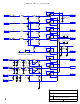

SERIES II, REV. H - Control System
4
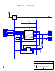
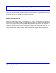
Pin 3 on U9 is left
unconnected on PCB
For U10
FWD
PSU
RFL
Low Thresh
C20
L8
C15
L9
NEAR U8
C8
0805
SOLDER SIDE
L3
1210 CHIP
C11
L7
C17
COMP. SIDE
C1
0805 CHIP
L10
2 1
U9
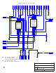
+5Vdc
C45
+
C42C41
+
C40C39
+
C38C37
+
C36C35
+
C34C21
+
C31C16
+
C28
NEAR U8
C2
0805
C12
+
C25
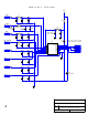
DtoUPC
DfromUPC
Dclk
ConvStrt
Isoltd 1
Isoltd 2
Isoltd 3
Isoltd 4
Isoltd 5
Isoltd 6
Isoltd 7
Isoltd 8
Vref
Cref
Vin1
AGND
Vin2
Vin3
Vin4
Vin5
Vin6
Vin7
Vin8
A0
DGND
TFS
RFS
Dout
Din
Dclk
ConvStart
Vdd
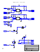
U10
R33
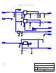
A. Sivacoe
Series II: Control System
H Analog Conversion Section
Date: May 14, 2004 Page: 1 of 1
Rev ID