
User's Manual


Warning!
1. Be sure to determine the correct wiring of the power supply polarity, wrong wiring will result in damage to the product and may endanger th
2. Before setup, make sure the voltage loading of the circuit switch complies with local regulations. Improper usage of electric
power and exceeding loading voltage will cause damage to the product.
3. This product is a low-power RF wireless carrier communications transmission systems, in order to reduce environmental obstacles lead
to remote insensitive, please try not to use the larger than the average residential space (details contact Dealer)
4. If for unavoidable necessary, must do installation under electrified condition, PLS connect LINE (Black) & NEUTRAL (White),
each to their corresponding wire first, turn off the switch, then connect the FIXTURE (Blue), & done!。
Button/Circuit(s) Settings
Name : 1 Circuit --- RF, Touched, 2-Way Cut
Model No. : LM-31
2M
Power & Loading: LM-31
2M (AC-110V, Max. Load 1,000W)
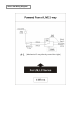
Wiring Diagram:
PLS check Annex A for the
detail & install switches
according to the site
environment
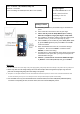
Setting / Control
1. PLS use [-] screwdriver (wound with tape) to dismantle the
panel.
2. Press & hold the Touch Sensor Area w/ your finger
3. Take a stick to press the Setup Button (feel a “click”),
when the red light on, let go your finger & setup stick.
4. The red light on, means the switch is under the setting mode
(window = 10 Sec.), if not, PLS repeat step (1) & (2).
5. Take a remote (ex. RC-07/RC-09), select Zone (Zone 1,2 or
3), press number (position) then press ON to send the RF
code to the switch.
6. When red led blinks then turns off, it means the setting is
completed. PLS use the remote to control the switch
ON/OFF, to confirm the setting.
7. PLS wait 30 sec. after installed the panel, till the sensor adapt
the thickness of the panel, then you may touch the panel to
switch ON/OFF the light.
8. Control: a.) Touch sensor area to turn ON/OFF the light.
b.) Remote: select Zone (Zone 1,2 or 3), press number