
Installation Instructions

Version 2-2018/ If there are any updates, no further notice will be given. | TBL 2 / 2
2]Depending on the electronic label used and the environmental conditions
2]-5] RF-RW202S supports this function
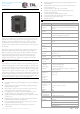
Port
1 POWER Power Indicator Lamp
2ETH Network Connection Indicator
3D O1 input indicator
4DO2 input indicator
5DO3 input indicator
6DO4 input indicator
7ANT1 Antenna Indicator
8ANT2 Antenna Indicator
9ANT3 antenna indicator
10ANT4 Antenna Indicator
11 antenna interface 4
12 antenna interface 3
13 antenna interface 2
14 antenna interface 1
15 Output Control DO Interface
16 Ethernet interface
17 Input Control DI Interface
18RS232 interface
19 power interface
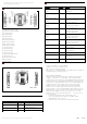
size
Packing list
category
number
Remarks
CSL-GFM1608-LN08-
A150
2
Optional length of DI/DO cable:
1.5m/3m/5m
CSL-GFM1604-LN04-
H150
1
Wire Length Optional: 1.5m/3m/5m
CSYV-GMTNC-GMN-
BNNN
1~4
Need to mark injection frequency line
length3mm outer diameter,
35db/100m attenuation
CSYV-GMTNC-GMN-
CNNN
1~4
Need to mark injection frequency line
length5mm outer diameter,
28db/100m attenuation
CSYV-GMTNC-GMN-
ENNN
1~4
Need to mark injection frequency line
length7mm outer diameter,
22db/100m attenuation
CSYV-GMTNC-GMN-
FNNN
1~4
Need to mark injection frequency line
length8mm outer diameter,
19db/100m attenuation
CSYV-GMTNC-GMN-
GNNN
1~4
Need to mark injection frequency line
length10mm outer diameter,
13db/100m attenuation
ARF-C04GFN-BBZZ
1~4
High performance 8dB (circular
polarized antenna
ARF-C03GFN-BB30
1~4
High Performance 6dB Circularly
Polarized Antenna
ARF-L08GFN-BB30
1~4
12 dB linear polarized antenna
CSL-GFM1602-LN02-
D150
1
The length of power cord is
1.5m/3m/5m.
RF-RW902
1
White card label, up to 15 meters
away
Optional Accessories
category
number
Remarks
RF-RW202/202S
1
Main engine type two choices
CSL-GFM1604-LN04-H150
1
Network Cable Length 1.5m
CSL-GFM1602-LN02-D150
1
Power cord length 1.5m
certificate
1
Paper Qualification Certificate
unit:mm
1, The product is limited to end user installation.
2, End user do not remove or install the product.
3,The product is use for Fixed Applications.
4.The product is professionally installed,The installer will be responsible for
ensuring that the proper antenna is employed.
FCC WARNING STATEMENT
Changes or modific ations not expressly approved by the party responsible for
compliance could void the user’s authority to operate the equipment. This
equipment has been tested and found to comply with the limits for a Class B digital
device, pursuant to Part 15 of the FCC Rules. These limits are designed to provide
reasonable protection against harmful interference in a residential installation. This
equipment generates uses and can radiate radio frequency energy and, if not
installed and used in accordance with the instructions, may cause harmful
interference to radio communications. However, there is no guarantee that
interference will not occur in a particular installation. If this equipment does cause
harmful interference to radio or television reception, which can be determined by
turning the equipment off and on, the user is encouraged to try to correct the
interference by one or more of the following measures: ‐‐ Reorient or relocate
the receiving antenna.
‐‐ Increase the separation between the equipment and receiver.
‐‐ Connect the equipment into an outlet on a circuit diffe rent from
that to which the receiver is connected.
‐‐ Consult the dealer or an experienced radio/TV technician for help.