
Installation & Assembly

2
2A
3
3
2
1
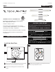
DRIVER
Connect the backplate wire to a suitable ground in
accordance with local electrical codes.
Connect the white driver wire to the neutral power line.
Connect the black driver wire to the hot power line.
Use the gray and purple dimming wires for 0-10v
dimming application.
1
2
3
4
4
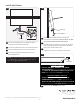
Install the Fixture
2B
6
5
Properly place the driver, all wires, and wire nut
connections into the canopy. Note: the driver for Span
24 must be installed into the electrical box.
Hook the top of the fixture to the top of the mounting
plate and swing the bottom of the fixture toward the
plate until it is flush with the wall.
Tighten the set screw at the bottom of the fixture.
7
ALLEN WRENCH
SET SCREW
7
8
Remove only the protective film.CLEAR
CLEAR FILM
2C
NOTE: The purple and gray wires are only used for
0-10v dimming. For all other applications, do not
connect the gray and purple wires.
WARNING: DO NOT REMOVE THE WHITE
ADHESIVE FILM
from the of this fixture. OnlySIDES
REMOVE THE TRANSPARENT PROTECTIVE FILM
which is located on the of the fixture.TOP AND BOTTOM
WARNING: DO NOT REMOVE THE WHITE
ADHESIVE FILM
from the TOP AND SIDES of this fixture.
Only
REMOVE THE TRANSPARENT PROTECTIVE
FILM
which is located on the BOTTOM of the fixture.
FOR DIRECT VERSIONS
FOR DIRECT/INDIRECT VERSIONS
©2020 Tech Lighting, L.L.C. All rights reserved. The Tech Lighting logo is a registered trademark of Tech Lighting.
Tech Lighting reserves the right to change specifications for product improvements without notification.
7400 Linder Ave., Skokie, IL 60077
T 847.410.4400 | F 847.410.4500
www.techlighting.com