
Installation & Assembly

1
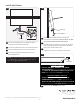
Install the Back Plate
1A
2
1
With the Allen wrench provided, back out (do not fully
remove) the set screw at the base of the fixture.
Remove the mounting plate from the back of the
fixture.
ALLEN WRENCH
SET SCREW
MOUNTING
PLATE
1
1B
3
3
Attach the mounting plate to the electrical box using
the two provided #8-32 screws .
3
3
WARNING: DO NOT REMOVE THE WHITE
ADHESIVE FILM
from the of this fixture. OnlySIDES
REMOVE THE TRANSPARENT PROTECTIVE FILM
which is located on the of the fixture.TOP AND BOTTOM
WARNING: DO NOT REMOVE THE WHITE
ADHESIVE FILM
from the TOP AND SIDES of this fixture.
Only
REMOVE THE TRANSPARENT PROTECTIVE
FILM
which is located on the BOTTOM of the fixture.
FOR DIRECT VERSIONS
FOR DIRECT/INDIRECT VERSIONS
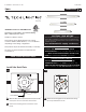
Installation Instructions for
920BCSPAN
Span
BATH
1.0
700BCSPAN
1.5
CAUTION RISK OF FIRE-
This product must be installed in accordance with the
applicable installation code by a person familiar with
the construction and operation of the product and the
hazards involved.
Use minimum 90°C supply conductors.
GP I :ENERAL RODUCT NFORMATION
This fixture are intended to be installed utilizing
NEC compliant junction boxes.
Suitable for damp locations.
This product may be dimmed with a low-voltage
electronic dimmer, TRIAC dimmer, or a 0-10V dimmer
depending on the wiring configuration.
This product may be mounted horizontally or vertically.
The driver for Span 24 must be installed into the
electrical box.
SAVE THESE INSTRUCTIONS!