
Installation Sheet

2
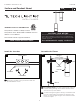
Wire the Fixture
Use the following wiring diagram to wire your fixture.
Make sure to cap 0-10V dimming wires if not being
used.
1
3A
N
H
0-10V
2
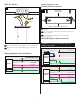
Standard 0-10V
EXTERNAL GROUND
GROUND
EXTERNAL NEUTRAL
EXTERNAL HOT
NEUTRAL WHITE
GREY/PINK
PURPLE
0-10V (-) DIM
0-10V (+) DIM
EXTERNAL GROUND
EXTERNAL NEUTRAL
EXTERNAL HOT
HOT BLACK
0-10V (-) DIM
0-10V (+) DIM
CROSSBAR
FIXTURE
Wiring Diagrams (Internal Drivers)
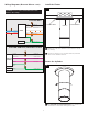
Wiring Diagrams (Remote Drivers)
Open remote driver junction box by removing 2
screws.
Connect conduit or Romex to junction box with the
proper fittings
Use the wiring diagrams to wire your fixture
accordingly.
1
2
3
Connect Power to the
Housing (Remote Drivers)
4A
ELECTRICAL
BOX COVER
REMOTE DRIVER ELECTRICAL BOX
1 1
2
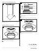
Hi-Lume 2 Wire
DRIVER
EXTERNAL GROUND
GROUND GREEN
EXTERNAL NEUTRAL
NEUTRAL WHITE
HOT BLACK
DRIVER
DRIVER
GROUND
CONNECTOR
TO DRIVER
THERMAL PROBE
HOUSING
Hi-Lume EcoSystem
EXTERNAL NEUTRAL
EXTERNAL HOT
NEUTRAL WHITE
HOT BLACK
PURPLE
PURPLE
DIM/DIGITAL BUS
DIM/DIGITAL BUS
EXTERNAL GROUND
GROUND
HOUSING
CONNECTOR
TO DRIVER
GROUND GREEN *
EXTERNAL HOT
WARNING: Do not connect red and blue wires from
fixture to line voltage.