
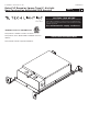
Installation Sheet
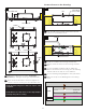
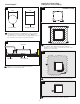

EXTERNAL GROUND
GROUND
EXTERNAL NEUTRAL
EXTERNAL HOT
NEUTRAL WHITE
GREY
PURPLE
0-10V (-) DIM
0-10V (+) DIM
EXTERNAL GROUND
EXTERNAL NEUTRAL
EXTERNAL HOT
HOT BLACK
0-10V (-) DIM
0-10V (+) DIM
HOUSING
DRIVER
4
2A
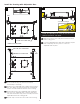
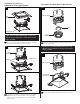
Connect Power to the Housing
Push the tab on the housing electrical box up and
remove the electrical box cover.
Install the conduit to the housing electrical box.
Run the power line wires into the housing electrical
box.
Use the thermally conductive tape to adhere the
driver to the bottom of the housing. Peel the backing
off both sides of the tape to ensure adhesion.
Use the following wiring diagram to wire your fixture.
Make sure to cap 0-10V dimming wires if not being
used.
ELECTRICAL
BOX COVER
2
3
1
TAB
2B
CONDUIT
4
B
5
DRIVER
6
6
1C
SCREW
HOUSING
COLLAR/HOLE
7
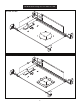
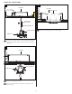
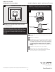
Adjust the collar's/hole's position (horizontal
position) by sliding the housing on adjustable bars.
When the desired location is achieved, tighten the
screws to lock the housing onto the adjustable bars.
NOTE: Notches in collar can be used to align multiple
housings using a laser or string.
7
7
COLLAR/HOLE
ADJUSTABLE BAR
HOUSING
6
6
6
6
6
6
NOTE: Round housing has a round hole only. No collar
is required.
7
6
SCREW
7
66
6