
Installation Sheet


2
SAVE THESE INSTRUCTIONS!
7400 Linder Ave, Skokie, 60077IL
847.410.4400
www.techlighting.com
© 2015 Tech Lighting, L.L.C. All rights reserved. The "Tech Lighting" graphic is
a registered trademark of Tech Lighting, L.L.C. Tech Lighting reserves the right
to change specifications for product improvements without notification.
A Generation Brands Company
5
4
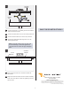
FIXTURE
BASE
CROSSBAR
ASSEMBLY
3
6
6
1C
3
4
5
1D
7
8
Place all wires and wire nut connections inside the
fixture base.
Align the fixture base holes with the crossbar assembly
holes. Secure the fixture in place by tightening the two
fixture screws.
CROSSBAR
ASSEMBLY
8
8
FIXTURE
SCREW
Connect the fixture to a suitable ground in accordance
with local electrical codes.
Connect the white driver wire to the neutral power line.
Connect the black driver wire to the hot power line.
Use the gray and purple dimming wires for 0-10V
dimming application.
NOTE: The purple and gray wires are only used
for 0-10v dimming. For all other applications,
cap off and do not connect the gray and purple
wires.
6