
Mini-Z M-Radon V2.1 Instruction Manual

2
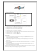
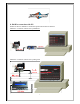
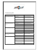
4. Connection Diagram:
Installation Tips:
1. Connect the speed control BEC wire at the back to the receiver position channel 2.
2. Connect power wire “A” to the motor “A” solder-tabs
3. Connect power wire “B” to the motor “B” solder-tabs
4. Connect power wire “C” to motor “C” solder-tabs
5. Connect the hall sensor cable between the speed control (underneath the solder taps) and motor
6. Connect power wire ”+” to battery “Plus” sign
7. Connect power wire “-“ to battery “Minus” sign
Point to notes:
1. All power wires should be connected properly according to the symbol indicator and avoid
creating solder bridges on the solder tab
2. Avoid soldering longer than 5sec per soldering joint when replacing the power wires on the
speed control
3. When connecting the battery to the speed control, please make sure the battery + or – should be
connected properly.
4. For the speed control BEC wire at the back, it can’t be used to connect USB device to PC. It
must use the signal wire at the front instead.
Please make sure to follow the above tips and notes to install the speed control, otherwise, the speed
control may be destroyed due to the improper connection of the wires.