INSTRUCTION MANUAL MODE D’EMPLOI BEDIENUNGSANLEITUNG
INSTRUCTION MANUAL · ENGLISH Warnings............................................................................... 3 Limited Warranty................................................................. 4 Connections.......................................................................... 6 Motor Connection................................................................ 6 Battery Connection............................................................. 7 ESC Power Switch........................................
WARNINGS Read the ENTIRE instruction manual to become familiar with the features of the product before operating. This is a sophisticated hobby product. It must be operated with caution and common sense and requires some basic mechanical ability. This product is not intended for use by children without direct adult supervision. Do not attempt disassembly, use with incompatible components or augment product in any way. This manual contains instructions for safety, operation and maintenance.
LIMITED WARRANTY Team Orion warrants to the original purchaser that the product purchased is free from defects in materials and workmanship at the date of purchase. Team Orion reserves the right to change or modify this warranty without notice and disclaims all other warranties, express or implied. This warranty is limited to the original purchaser and is not transferable. Replacement as provided under this warranty is the exclusive remedy of the purchaser.
Team Orion will not be liable for special, indirect or consequential damages, loss of profits or production or commercial loss in any way connected with the product, whether claim is based in contract, warranty, negligence, or strict liability. Further, in no event shall the liability of Team Orion exceed the individual price of the product on which liability is asserted.
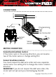
CONNECTIONS C B A + Rear View Programming Port LED Fan Connector RX Sensor Port C B A Setup On/Off MOTOR CONNECTION Sensorless brushless motors If the motor spins in the wrong direction, you can reverse two of the motor wires or change setting #12 Sensor brushless motors You must respect the ABC wire order and use a separate sensor wire. Use setting #12 to change the motor rotation direction. WARNING! If you do not respect the ABC wire order, the motor will not spin and you risk damaging the ESC.
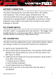
BATTERY CONNECTION This ESC is designed for use with 2S (7.4V) to 4S (14.8V) LiPo batteries. Use of other types of batteries is not recommended and may cause damage to the ESC. Only use batteries equipped with compatible connectors. Using adapters may create extra electrical resistance and cause damage to the ESC. ESC POWER SWITCH The ESC switch is equipped with two buttons. The bigger LED backlit button is used to power ON or OFF the ESC and the smaller button is used for calibration/setup.
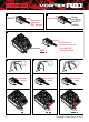
1 2 ON/OFF Press and hold the SET button Keep pressing the SET button Switch ON 3 Release as soon as soon as the red LED starts to blink LED 4 5 Press once LED 8 6 Press once LED Press once LED Copyright Team Orion © 2015
PROGRAMMING YOUR ESC 1 Switch ON Connect the battery Enter Programming Mode Reset to factory default settings OR 2 2 Press the SET button for 1s Press the SET button for 5s LED blinks Select the parameter you wish to modify 3 3 Press the SET button 1 time to select the 1st parameter... ...press the SET button 2 times to select the 2nd parameter etc.
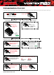
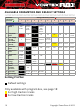
AVAILABLE PARAMETERS AND DEFAULT SETTINGS Parameter (indicated by green LED ) Setting (indicated by red LED 1 2 3 4 5 ) 6 7 8 9 6% 8% 10% Custom 1-100% Standard Parameters (adjustable with the ESC setup button) 1 Running Mode Forward with Brake Forward/ Reverse with Brake Forward with Brake (Sensor) Forward/ Reverse with Brake (Sensor -2% -1% 0% 2% 4% 2 Drag Brake Force 3 Low Voltage Cut-Off Threshold 0 2.8V/Cell 3.0V/Cell 3.2V/Cell Custom 3.5-12.
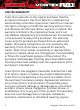
Thank you for purchasing a Team Orion Brushless ESC. This ESC features the latest brushless technologies. Our World Championship winning development team has spent countless hours developing this ESC so that you can experience ultimate performance. Please read these instructions thoroughly before using the ESC. FEATURES • • • • • • Designed for on-road and off-road 1/8 scale cars 6V or 7.
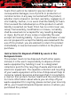
repeatedly with a 1 second pause (xx-xx-xx). 2. Radio signal issue: as it is powered on and the ESC checks the radio signal input. If an issue is detected, the ESC emits one beep tone repeatedly with a 2 second pause (x-x-x). ESC PARAMETERS SETUP You can adjust several parameters by using the setup button located on the switch or by using the optional program box (ORI65153). The green flashing LED indicates the parameter and the red flashing LED indicates the setting value.
flash = setting 1, two flashes = setting 2 and so on. Press the button to switch between the different available settings. G. Press and hold the setup button for 3 seconds to save the modification. H. Power the ESC off and back on to make the parameter change effective. Note: you can only change one setting at a time, after each modification you need to power the ESC off and back on to make the parameter change effective and be able to modify another parameter. ADJUSTABLE PARAMETERS 1.
is moved to the forward position, the car will immediately accelerate forward. ›› Setting 1 and 2 for sensorless motors ›› Setting 3 and 4 for sensor motors 2. Drag Brake Force This parameter sets the amount of brake automatically applied when the throttle returns to the neutral position. This simulates the engine braking effect of a real car. Note: some 1/8 brushless motors may have a lot of “autobrake” due to their construction. In that case, -1% and -2% setting can help to reduce the auto-brake effect.
4. Start mode “punch” This parameter sets the initial throttle punch when the car accelerates. Level 1 gives a very soft initial acceleration and level 9 gives a very strong initial acceleration. Warning! Stronger acceleration will also result in higher ESC and motor running temperature. Check the motor and ESC temperature and adjust the parameter to keep temperature within safe limits. ›› Setting value from 1 to 9 5. Max Brake Force This parameter sets the maximum braking force.
8. Neutral Range This parameter sets the throttle sensitivity around the neutral point. A higher value means that the throttle will have to be moved further for the car to move forward, backward or brake. ›› Setting value from 6% to 12% 9. Timing This parameter sets the motor drive current timing. A lower value decreases performance but increases efficiency and run time, a higher value increase performance but lowers efficiency and run time.
14. BEC Voltage This parameter sets the voltage output of the ESC BEC system that powers the electronics in your car. WARNING! Using 7.2V will increase the servo performance but requires compatible electronics (regular electronics only work with 6V). Using 7.2V with 6V electronics can damage them. ›› Setting value 6V or 7.
PC SOFTWARE The PC computer software is used to modify the ESC settings and update/modify the ESC or program box firmware. • You can download the PC software for free from our website www.teamorion.com/R10-downloads.html • The program box is required to connect your ESC to the computer/PC software. • The PC software allows you to update/modify your program box and ESC firmware. • The PC software allows you to modify all of the ESC settings (as with the program box).
Notes www.teamorion.
BEDIENUNGSANLEITUNG · DEUTSCH Warnungen......................................................................... 21 Garantie.............................................................................. 22 Anschlüsse.......................................................................... 24 Akku-Anschluss.................................................................. 25 Regler Ein/aus-Schalter..................................................... 25 Regler-Kalibrierung...................................
WARNUNGEN Lesen Sie die Anleitung vor dem Gebrauch vollständig durch, damit Sie alle Eigenschaften des Produkts verstehen. Dies ist ein hochentwickeltes Hobby-Produkt. Es muss mit Vorsicht und gesundem Menschenverstand betrieben werden und benötigt gewisse mechanische Grundfähigkeiten. Dieses Produkt eignet sich nicht für die Verwendung durch Kinder ohne direkte Überwachung eines Erwachsenen.
GARANTIE Team Orion garantiert, dass das Produkt zum Zeitpunkt des Kaufs frei von Material- und Montagefehlern ist. Team Orion behält sich das Recht vor, diese Garantiebestimmungen ohne Ankündigung zu ändern oder modifizieren und widerruft dann bestehende Garantiebestimmungen. Die Garantie wird nur dem Erstkäufer (Käufer) gewährt und kann nicht übertragen werden. Der Anspruch des Käufers besteht in der Reparatur oder dem Tausch im Rahmen dieser Garantie.
Team Orion ist nicht für direkte oder indirekte Folgeschäden, Einkommensausfälle oder kommerzielle Verluste, die in irgendeinem Zusammenhang mit dem Produkt stehen verantwortlich, unabhängig ab ein Anspruch im Zusam- menhang mit einem Vertrag, der Garantie oder der Gewährleistung erhoben werden. Team Orion wird darüber hinaus keine Ansprüche aus einem Garantiefall akzeptieren, die über den individuellen Wert des Produktes hinausgehen.
ANSCHLÜSSE C B A + Rückansicht ProgrammierAnschluss LED Lüfter Anschluss Sensor Anschluss C B A RX Setup On/Off Sensorless Brushless Motoren: Wenn der Motor in die falsche Richtung dreht, vertauschen Sie zwei beliebige Anschlusskabel des Motors oder verwenden Sie die Einstellung #12. Sensor Brushless Motoren: Sie müssen die Reihenfolge A-B-C der Motoranschlusskabel beachten und ein Sensorkabel verwenden. Ändern Sie die Drehrichtung mit der Einstellung #12.
AKKU-ANSCHLUSS Der Regler ist für den Gebrauch mit 2S (7.4V) bis 4S (14.8V) Akkus vorgesehen. Der Gebrauch von anderen Akkus wird nicht empfohlen und kann zur Beschädigung des Reglers führen. Verwenden Sie nur die Original-Stecker. REGLER EIN/AUS-SCHALTER Der Schalter des Reglers ist mit zwei Tasten ausgestattet. Die grössere, LED beleuchtete Taste ist für das Ein-/Ausschalten, die kleinere Taste für die Kalibrierung und Einstellungen.
1 2 EIN/AUS SET Taste drücken und halten SETTaste stetig halten Einschalten 3 Loslassen, sobald die rote LED blinkt LED 4 5 1 mal drücken LED 26 6 1 mal drücken LED 1 mal drücken LED Copyright Team Orion © 2015
REGLER PROGRAMMIEREN 1 Einschalten Akku einstecken Programmiermodus starten Alle Einstellungen zurücksetzen OR 2 2 SET Taste während 5s drücken SET Taste während 1s drücken LED blinkt 3 4 5 6 Wählen Sie den Parameter, den Sie ändern möchten 3 ...drücken Sie die SET Drücken Sie die SET Taste 2 mal, um den Taste 1 mal, um den ersten Parameter zu zweitenParameter zu wählen... wählen... LED blinkt 1 mal LED blinkt 2 mal 3 Drücken Sie die SET Taste während 3s, um den Parameter zu ändern.
VERFÜGBARE EINSTELLUNGEN UND STANDARDWERTE Parameter (grüne LED Einstellung (rote LED ) 1 2 3 4 5 ) 6 7 8 9 6% 8% 10% Custom 1-100% Standard Parameter (einstellbar mit ein/aus-Schalter) 1 Fahrmodus 2 AutomatikBremse -2% -1% 0% 2% 4% 3 Grenzwert Abschaltspannung 0 2.8V/Cell 3.0V/Cell 3.2V/Cell Custom 3.512.6V 4 Startmodus (Punch) Level 1 Level 2 Level 3 Level 4 Level 5 Level 6 Level 7 Level 8 Level 9 5 Maximale Bremsstärke 12.5% 25% 37.5% 50% 62.5% 75% 87.
Vielen Dank für den Kauf eines Team Orion Brushless Fahrtenreglers. Dieser Fahrtenregler ist mit der aktuellsten Technologie ausgerüstet. Unser Team, das mit zahlreichen Weltmeistertiteln ausgezeichnet worden ist, hat unzählige Teststunden in den Regler investiert, um die höchstmögliche Leistung zu erzielen. Lesen Sie diese Anleitung genau durch, bevor Sie den Regler verwenden. EIGENSCHAFTEN • • • • • • Entwickelt für On-Road und Off-Road 1/8er Fahrzeuge 6V oder 7.
Empfangssignal, sobald er eingeschaltet ist. Falls ein Problem besteht, ertönt wiederholt ein Signalton im Abstand von 2 Sekunden (x-x-x). REGLER-EINSTELLUNGEN Sie können Einstellungen mit Hilfe der Setup Taste auf dem Ein-/Aus-Schalter oder mit der optionalen Programmierbox vornehmen (ORI65153). Die grüne LED zeigt den gewählten Parameter und die rote LED den Wert des Parameters. Benutzerspezifische Werte können nur mit Hilfe der optionalen Programmierbox vorgenommen werden.
drücken und halten Sie die Setup -Taste während 3 Sekunden, um die Änderung zu speichern. 8. Schalten Sie den Regler aus und wieder ein, um die neue Einstellung zu aktivieren. Bitte beachten: Sie können jeweils nur eine Einstellung verändern. Nach jeder Veränderung muss der Regler einund ausgeschaltet werden. VERFÜGBARE EINSTELLUNGEN 1. Betriebsmodus / “Blinky” Modus Sie können die Rückwärts-Funktion ein- und ausschalten. Es gibt zudem Sensor- und Sensorless-Modi.
Vorwärtsposition übergehen, fährt das Fahrzeug umgehend vorwärts. ›› Einstellung 1 und 2 für Sensorless-Motoren ›› Einstellung 3 und 4 für Sensor-Motoren 2. Automatik-Bremse Bremst das Fahrzeug automatisch ab, wenn der Gashebel in die Neutralposition geführt wird. Dies simuliert die Motorbremse eines echten Fahrzeugs. Dies kann zu besserem Einlenkverhalten und besseren Fahrgefühl führen. Bemerkung: einige 1/8er Brushless-Motoren weisen eine sehr starke Motorbremse auf.
die Werte in der Programmierbox die Spannung des gesamten Akkus und nicht der einzelnen Zellen. Warnung! Ein zu tiefer Wert kann den Akku beschädigen! ›› Von 0 (keine Abschaltung) bis 3.2V/Zelle 4. Startmodus “Punch” Diese Einstellung ermöglicht es, die Beschleunigungscharakteristik des Fahrzeugs zu verändern. Level 1 ergibt eine sehr feine Beschleunigung und Level 9 beschleunigt sehr stark aus dem Stand. Achtung! Stärkerer Punch resultiert in höherer Regler- und MotorTemperatur.
7. Minimalbremskraft Mit dieser Einstellung können Sie die minimale Bremskraft beim Betätigen der Bremse verändern. Ein höherer Wert ergibt stärkere Bremskraft, belastet aber den Regler und Motor stärker und kann zu Kontrollverlust führen. ›› Einstellung von Auto-Bremse bis 25% 8. Neutral-Bereich Diese Einstellung betrifft die Empfindlichkeit des Regelverhaltens um den Neutralpunkt.
vertauschen. Bei Sensormotoren müssen Sie zwingend die Anschlussreihenfolge ABC einhalten und die Drehrichtung mit dieser Einstellung änern. ›› Einstellungen CW (im Uhrzeigersinn) oder CCW (gegen den Uhrzeigersinn 13. LiPO Cells Mit dieser Einstellung können Sie manuell die Anzahl Zellen Ihres Akkus erfassen. Der Regler verwendet diese Einstellung zusammen mit der Einstellung #3 (Akku-Abschaltspannung), um eine Tiefentladung des Akkus zu verhindern. ›› Einstellungen Auto oder 2-3-4S LiPo 14.
PROGRAMMIERBOX Die optionale Programmierbox erlaubt es, die Einstellungen Ihres Reglers zu ändern, sowie die Firmware zu aktualisieren (mit Hilfe der PC-Software). • Die Programmierbox wird verwendet, um den Regler zusammen mit der PC-Software zu verwenden. • Die Firmware der Programmierbox ist unabhängig von der Regler-Firmware. Je nach Regler muss die Firmware der Programmierbox oder des Reglers mit Hilfe der PC-Software aktualisiert werden, damit sie zusammen funktionieren.
EINSTELLUNGSPROFILE Der Regler kann 3 verschiedene Profile speichern. Hierzu benötigen Sie die optionale Programmierbox. Im Regler sind 3 Grundeinstellungen gespeichert: Profil #1: Standard-Gebrauch Profil #2: Für Rennstrecken mit viel Grip Profil #3: Für Rennstrecken mit wenig Grip www.teamorion.
MODE D‘EMPLOI · FRANCAIS Mises en garde................................................................... 35 Garantie.............................................................................. 36 Branchements.................................................................... 37 Calibrage du variateur...................................................... 38 Programmation du variateur........................................... 40 Paramètres du variateur et réglages par défaut...........
MISES EN GARDE Lisez la totalité du mode d’emploi afin de vous familiariser avec les caractéristiques du produit avant de le faire fonctionner. Ceci est un produit de loisirs sophistiqué. Il doit être manipulé avec prudence et bon sens et requiert des aptitudes de base en mécanique. Ce produit n’est pas destiné à être utilisé par des enfants sans la surveillance directe d’un adulte. N’essayez pas de démonter le produit, de l’utiliser avec des composants incompatibles ou d’en améliorer les performances.
GARANTIE LIMITEE Team Orion se réserve le droit de modifier les instructions, les garanties et autres documents à tout moment. Cette garantie n’est valable que pour l’acquéreur initial du produit et n’est pas transmissible. Un échange tel que prévu par cette garantie, n’est possible que pour l’acquéreur initial. Cette garantie couvre uniquement les produits achetés chez un revendeur agrée. Les transactions tierces ne sont pas couvertes par cette garantie.
manque à gagner, baisse de production ou perte commerciale liée d’une quelconque façon au produit et ce, qu’une telle réclamation soit fondée sur un contrat, une garantie, une négligence ou une responsabilité directe. Par ailleurs, la responsabilité de Team Orion ne saurait en aucun cas dépasser le prix unitaire du produit pour lequel elle est engagée.
BRANCHEMENTS C B A + Vue arrière Port de programmation LED Prise ventilateur RX Port sensor C B A Réglage On/Off Moteur brushless sensorless Si le moteur tourne à l’envers, inversez deux des trois fils moteur ou modifiez le réglage #12. Moteur brushless avec sensor Vous devez respecter l’ordre des fils ABC et utiliser un câble sensor. Modifiez le sens de rotation à l’aide du réglage #12.
BRANCHEMENT DE LA BATTERIE Ce variateur est conçu pour les batteries LiPo de 2S à 4S (7.4-14.8V). L’utilisation d’autres types de batteries n’est pas recommandé. Utilisez uniquement des batteries équipées de connecteurs compatibles. INTERRUPTEUR Le variateur est équipé d’un interrupteur avec deux boutons. Le bouton principal est rétro-éclairé avec une LED et le deuxième bouton sert au réglage du variateur. CALIBRAGE DU VARIATEUR Le variateur doit être calibré pour le signal de l’émetteur.
1 2 ON/OFF Maintenir pressé Maintenir pressé Enclencher 3 Relâcher lorsque la LED rouge clignote LED 4 5 Pressez une fois LED 44 6 Pressez une fois LED Pressez une fois LED Copyright Team Orion © 2015
PROGRAMMATION DU VARIATEUR 1 Enclencher Brancher la batterie Mode de programmation Remise en configuration d‘usine OR 2 2 Pressez le bouton pendant 1sec Pressez le bouton pendant 5sec La LED clignote Sélectionnez le paramètre que vous voulez modifier 3 3 Pressez une fois pour sélectionner le 1er paramètre La LED clignote 1 fois 4 5 6 Pressez deux fois pour sélectionner le 2ème paramètre 3 La LED clignote 2 fois Pressez pendant 3sec pour modifier le paramètre Modifiez le réglage en pressant le
PARAMÈTRES DU VARIATEUR ET RÉGLAGES PAR DÉFAUT Parameter (indicated by green LED ) Setting (indicated by red LED 1 2 3 4 5 ) 6 7 8 9 6% 8% 10% Custom 1-100% Standard Parameters (adjustable with the ESC setup button) 1 Running Mode Forward with Brake Forward/ Reverse with Brake Forward with Brake (Sensor) Forward/ Reverse with Brake (Sensor -2% -1% 0% 2% 4% 2 Drag Brake Force 3 Low Voltage Cut-Off Threshold 0 2.8V/Cell 3.0V/Cell 3.2V/Cell Custom 3.5-12.
Nous vous félicitons pour l’achat d’un variateur brushless Team Orion. Ce variateur est équipé des technologies les plus récentes. Notre team champion du monde a passé de longues heures à développer ce produit afin que vous puissiez bénéficier des performances les plus élevées qui soient. Veuillez lire attentivement ce mode d’emploi avant d’utiliser le variateur. CARACTÉRISTIQUES • Conçu pour les voitures piste ou tout-terrain à l’échelle 1/8. • BEC 6V ou 7.
SIGNAUX SONORES 1. Problème d’alimentation: le variateur contrôle la tension de la batterie lorsqu’il est enclenché. Si un problème est détecté, le variateur émet deux signaux sonores avec 2 secondes de pause entre les répétitions (xx-xx-xx). 2. Problème de signal radio: le variateur contrôle le signal radio lorsqu’il est enclenché. Si un problème est détecté, le variateur émet un signal sonore avec 2 secondes de pause entre les répétitions (x-x-x).
paramètre à l’autre. E. Pour modifier le paramètre, pressez sur le bouton jusqu’à ce que la LED rouge clignote. F. La LED rouge clignote, indiquant le réglage actuel. Un flash = réglage 1, deux flash = réglage 2 et ainsi de suite. Pressez sur le bouton pour passer d’un réglage à l’autre. G. Appuyez sur le bouton pendant 3 secondes pour sauvegarder la modification. H. Eteignez puis rallumez le variateur pour valider la modification. NB : Vous ne pouvez modifier qu’un paramètre à la fois.
soit totalement arrêtée. Une fois la voiture à l’arrêt, relâchez le manche des gaz puis tirez/poussez le en position marche arrière à nouveau pour enclencher la marche arrière. Lorsque la voiture recule ou pendant que vous freinez, si vous tirez/poussez le manche des gaz en position marche avant, la voiture repart en avant instantanément. Réglage 1 et 2 pour moteurs Sensorless Réglage 3 et 4 pour moteurs Sensor 2.
Réglage de OFF à 3.4V/élément ou custom pour la tension totale de la batterie (défaut 3.2V/élément) 4. Start mode “punch” (puissance accélération) Ce paramètre défini la puissance de l’accélération. Le niveau 1 donne une accélération peu puissante et le niveau 9 donne l’accélération la plus puissante. Attention ! Une valeur élevée provoque plus de contraintes sur le moteur et le variateur, assurez-vous qu’ils ne surchauffent pas ! ›› Réglage de 1à 9 5.
›› Réglage de valeur drag brake (frein moteur) à 40% 8. Neutral range (sensibilité point mort) Ce paramètre défini la sensibilité des gaz autour du neutre. Une valeur plus élevée fait qu’il faut utiliser plus de débattement de la commande des gaz pour que la voiture avance, recule ou freine. ›› Réglage de 6% à 12% 9. Timing (avance) Ce paramètre défini l’avance appliquée au courant d’alimentation du moteur. Une valeur plus élevée augmente les performances mais diminue le rendement et l’autonomie.
surdécharge de la batterie et d’éventuels dommages. ›› Réglage de 2 à 4 éléments (7.4-14.8V) et auto calculate 14. BEC Voltage (tension alimentation BEC) Ce paramètre défini la tension de sortie du circuit BEC qui alimente l’électronique de votre modèle. Attention ! Avec le réglage 7.2V on augmente les performances des servos, mais cela nécessite une électronique compatible (le standard est 6V). Si on utilise 7.2V avec du matériel 6V on peut l’endommager. ›› Réglage 6V ou 7.
LOGICIEL PC Le logiciel PC sert régler les paramètres du variateur et modifier/mettre à jour le micrologiciel du variateur ou du boîtier de programmation. • Le logiciel PC est disponible gratuitement sur notre site www.teamorion.com • Le boîtier de programmation est nécessaire pour pouvoir raccorder le variateur au PC. • Le logiciel PC vous permet de modifier/mettre à jour le micrologiciel du variateur et du boîtier.
NOTES www.teamorion.