
User's Manual

13
speaker installation
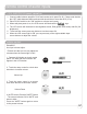
installing planning
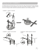
Front of Room
Receiver
Amplifier
Ceiling Sensor
Wall Speakers
Front of Room
Receiver
Amplifier
Ceiling Sensor
r
r
Wall Speakers
Front of Room
Ceiling Sensor
Listening Area
List
A
rea
Ceiling Speakers
Front of Room
Ceiling Sensor
Listening Area
Ceiling Speakers
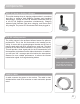
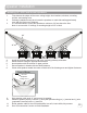
• Amplier/Receiver: Choose location the based on accessibility requirements and wiring
constraints for power, speakers, and audio devices.
• Ceiling Sensor: Locate in the center of the ceiling; maintain line of sight; keep away from direct
light and electrical interference.
• Speakers: Mark location for wall mount vs. ceiling mount, and conrm wiring run to the amplier.
Ensure speakers evenly cover the listening area.
• Integrations/Connections: Conrm location of other systems you plan to connect to the amplier
such as audio devices, intercom connections, re alarm, noting how the wiring needs to run.
• Microphones/Charger: Conrm microphone charging location for daily use/charging.
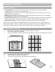
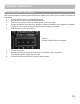
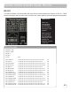
ceiling speaker installation
1. Determine the listening area based on where students are seated.
2. Divide listening area into quadrants.
3. Locate and identify the center most tile in each quadrant to ensure even distribution of sound.
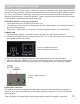
4. Lay ceiling tile face down on clean at surface.
5. Lay tile bridge on ceiling tile and center it.
6. Trace and cut the large hole using a keyhole or drywall saw.
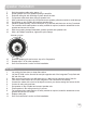
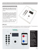
The IMA-120 has two channels of amplied audio, rated for a minimum 4-ohm speaker load (two
8-ohm speakers each). There is one blue phoenix style speaker connector on the back panel, provid-
ing one pair of speaker terminals. When using 4 speakers they must be wired in parallel.
Figure 2: Cutting the Tile
Tile Bridge
Back Side of
Ceiling Tile
Cut Out Area
SP-628