From the Makers of TTC-895 ASSEMBLY & INSTRUCTION MANUAL 10 +
Content Introduction ............................................................................................................ 1 Tools You May Need ................................................................................................. 1 Mechanical Parts List ................................................................................................ 1 Plastic Parts ...........................................................................................................
Introduction The mechanical coding wheel is the heart of the Mech.5 Mechanical Coding Robot. It steers its coded courses and programmed tasks. Coding is executed effortlessly by snapping the coding buttons onto the coding wheel directing your robot to perform its basic functions – move forward, backward, right or left, spin or pause.
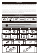
Plastic Parts Cut off the plastic parts when they are required. Do not cut them in advance.
Please Read Before Assembly Remove burrs Unnecessary burrs Unnecessary burrs Correct Incorrect Some burrs are left at the edge of plastic parts after cutting them off. Make sure the burrs are completely removed to avoid operation malfunction. Trim off the burrs ONLY. Do not trim off the protrusion of the original plastic parts. All features of parts should be kept completely. Fasten tapping screws Use corresponding (size-compatible) screwdriver.
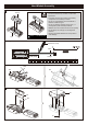
Head Module Assembly 1 • Installation, removal and replacement of batteries should be carried out by an adult or under adult supervision. AAA(x2) • Avoid short circuiting the contacts in the battery compartment or the battery terminals. • Do not mix used batteries and new batteries or batteries of different types. • Do not mix alkaline, standard (carbon-zinc) , or rechargeable (nickel-cadmium) batteries. • Batteries are to be inserted with the correct polarity.
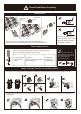
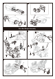
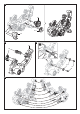
3 4 B1 E12 C4 C1 P7 Gear Box Module Assembly 2 1 Tip E18 A2 C3 P7 C3 E15 E18 P7 E15 P7 3 D2 P6 A8 P6 5 P2 (Black)
4 6 P10 A4 Correct C17 P13 P7 Incorrect P1 A10 7 B7 B5 3 2 D12 1 Correct Correct Incorrect Incorrect 5 P4 (Orange) P5 (Black) Incorrect 8 P3 (Yellow) P3 (Yellow) 1 2 P5 (Black) 3 P3 (Yellow) P7 P4 (Orange) P3 (Yellow) P2 (Black) 6
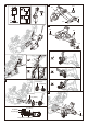
Rear Gear Box Testing (1) Head Module Power Supply Cable 1 Connect the power supply cable of assembled head (Refer to page 4: Head Module Assembly) to the terminal base. 2 Move the switch to the right to turn the power on. 1 3 The gear will run counterclockwise as illustration. 3 4 Switch off and remove the power supply cable after the testing. If the gear box doesn’t run smoothly or there is abnormal noise, please go back to page 5 step 1 to reassemble.
13 E9 1 2 E14 B4 14 15 Tip A5 C2 E15 P7 16 8
17 Rear Gear Box Testing (2) 1 Connect the power supply cable of assembled head (refer to page 4: Head Module Assembly) to the terminal base. 2 Move the switch to the right to turn the power on. P7 3 The gear will run counterclockwise as illustration. 4 Switch off and remove the power supply cable after the testing. If the gear box doesn’t run smoothly or there is abnormal noise, please go back to page 5 step 1 to reassemble.
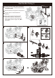
20 B16 C18 P8 Incorrect Correct C14 21 B12 B2 A7 G1 A1 22 C13 G2 x2 10
23 B14 B15 24 25 E22 1 P7x3 2 E21 1 2 11
30 32 A11 Incorrect Correct 33 Completed 31 2 1 12
Accessory Module Assembly MODULE MODULE 1 2 P11 P11 C7 C8 MODULE 3 P9 MODULE E17 4 C19 E16 x2 C20 Coding Wheel Assembly A3 F 13
About the Coding Wheel Backward coding track Assignment coding track CODING WHEEL Start point Left coding track (Right coding track is on the other side) How to Install Coding Buttons Correct Assignment coding button (Only for forklift) Incorrect E4 Correct Assignment coding button E5 Incorrect E7 Correct Incorrect Backward coding button Correct Incorrect E6 E8 45 degree angle coding button 90 degree angle coding button Correct Incorrect Correct 14 Incorrect Correct Incorrect
How to Install the Coding Wheel 1 Unlock Coding Wheel Clips Top View PUSH PUSH PUSH PUSH PUSH PUSH Push the four clips as shown PUSH PUSH 2 1 Rotate clips outward to unlock. 1. 2 Tilt shaded section forward. 2.
3 Incorrect Correct Coding Wheel Coding Wheel Set the “Start Point” to Home Postion Correct Incorrect 16
4 Pull the four clips outward to secure coding wheel.
How the Coding Buttons Work 45° Right Turn 90° Right Turn E6 E8 Right Track Right Coding Track 45° Left Turn 90° Left Turn E6 E8 Left Coding Track Left Coding Track 18
45° Back Right Turn 90° Back Right Turn Right Coding Track Sp Right Coding Track ac e E6 E7x2 E8 Backward Track Backward Track 45° Back Left Turn E7x3 90° Back Left Turn Backward Track Backward Track E7x2 ce Spa E8 E6 E7x3 Left Coding Track Left Coding Track 19
Drawing-bot Assembly 1 D10 D9 2 3 E19 D3 C15 D7 21
4 Marker Pen (Fine) E19 Scale 1:1 3.7 5” (9.5 cm ) 3.75” (9.5 cm) Video Tips To better understand the assembly and operations of each project, view the sample video listed in Video Tips on the project page.
Video Tips Drawing-bot View a video on this project at https://www.elenco.com/teachtech/ Parts Required: E5x10 CODING E8x5 Insert the Coding buttons as shown. Note the position and sequence on both sides of the coding CODING WHEEL CODING WHEEL E5 Left side Right side 10 pcs Start point Start point E8 5 pcs First test the program with the pen cap on. Place the unit on a 2.5’ x 2.5’ piece of paper. Turn the Draw-BOT on, it moves forward then draws a 13’ diameter circle.
Forklift-bot Assembly 1 D10 D9 D18 E3 D19 E3 2 3 E19 D7 C16 1 2 24 E19
4 C12 MODULE 1 C11 MODULE 2 E10 E11 B10 B10 5 C10 C9 C6 C5 25
Video Tips Forklift-bot View a video on this project at https://www.elenco.com/teachtech/ Parts Required: E4x2 E5x6 E6x5 E7x6 E8x11 Insert the E8 and E5 buttons as shown. Insert the coding buttons as shown. Note theCODING position the sequence both sides of the coding wheel. Note the on position the sequence on both sides of the coding wheel.
Throwing-bot Assembly 1 Tip : disassemble assembly as shown below E10 E11 C6 C5 C9 C10 C11 C12 2 D15 MODULE 3 MODULE 3 Refer to page 12 D14 D8 MODULE 3 27
3 2 D7 E19 1 C15 4 4 D13 3 E20 D13 2 3 E20 2 1 E19 28
Throwing-bot Video Tips View a video on this project at https://www.elenco.com/teachtech/ Parts Required: E5x2 CODING E6x3 E8x10 Insert the coding buttons as shown. Note the position the sequence on both sides of the coding wheel. CODING WHEEL E6 CODING WHEEL E6 Left side Right side 2 pcs 1 pc E8 E5 E8 4 pcs 2 pcs 6 pcs MODULE 4 For safety concern, users should not use any dangerous materials as throwing object, such as steel balls or sharp items. Trouble Shooting 1.
Gripper-bot Assembly 1 D10 D9 E3 D18 E3 2 D19 C5 C6 MODULE 1 MODULE 2 D4 D5 C10 C9 30
3 E19 D7 4 6 MODULE 3 7 5 C16 E19 31
Video Tips Gripper-BOT View a video on this project at https://www.elenco.com/teachtech/ Parts Required: E5x9 CODING E6x2 E7x6 E8x9 Insert the coding buttons as shown. Note the position the sequence on both sides of the coding wheel. CODING WHEEL Left side E8 4 pcs Trouble Shooting E7 E5 6 pcs 9 pcs E6 E6 1 pc 1 pc CODING WHEEL Right side E8 5 pcs 1.
Soccer-bot Assembly 1 MODULE 1 MODULE 3 D4 3 2 D5 D3 E20 E20 Gear Box 2 D10 D9 33
3 5 4 E19 C16 D7 6 E19 D18 D19 C9 C10 C11 C12 34
Soccer-bot Video Tips View a video on this project at https://www.elenco.com/teachtech/ Parts Required: E5x4 CODING E8x5 Insert the coding buttons as shown. Note the position the sequence on both sides of the coding wheel. CODING WHEEL E5 Left side CODING WHEEL Right side 4 pcs E8 E8 2 pcs 3 pcs MODULE 4 Trouble Shooting 1. If it does not follow the coding program correctly, please go back to page 34 step 4 to check if part C16 is assembled in the right way. 2.
How to Replace the Batteries 1 REMOVE 3 2 REMOVE Battery( AAA) x 2 Insert “–” on battery first Removal and replacement of batteries should be carried out by adults or under adult supervision. Avoid short circuiting the contacts in the battery compartment or the battery terminals. Do not mix used batteries and new batteries or batteries of different types. Do not mix alkaline, standard (carbon-zinc) , or rechargeable (nickel-cadmium) batteries. Batteries are to be inserted with the correct polarity.
Trouble Shooting 1. Ensure all coding buttons are assembled correctly (refer to page 14). 2. Ensure the coding wheel is assembled correctly (refer to pages 15–17, steps 1 – 6 ). 3. If the robot does not move smoothly or appropriately when turning right/left or stopping, please go back to pages 9–10 and ensure steps 18 – 21 are correctly executed. 4.
150 Carpenter Ave. Wheeling, IL 60090, USA (847) 541-3800 or (800) 533-2441 elenco.com CHOKING HAZARD. Small Parts. Not for children under 3 years old. No part of this book shall be reproduced by any means: electronic, photocopying, or otherwise without written permission from the publisher. Printed in Taiwan Patents Pending Not responsible for typographical errors. Teach TechTM is a trademark of Elenco Electronics Inc. Copyright© 2019 Elenco Electronics Inc. All rights reserved.