2i blu Module User Guide The information contained in this document is subject to change without notice. TDK Systems Europe makes no warranty of any kind with regard to this material including, but not limited to, the implied warranties of merchant ability and fitness for a particular purpose. TDK Systems Europe shall not be liable for errors contained herein or for incidental or consequential damages in connection with the furnishing, performance, or use of this material.
Contents BEFORE YOU BEGIN.................................................................................................................................................................... 3 SAFETY GUIDELINES ................................................................................................................................................................... 3 RF APPROVALS ...........................................................................................................................
Before You Begin Congratulations on your purchase of the TDK Systems blu2i Module. The Module is designed to be built into a device and to provide a simple, low cost Bluetooth interface. The module is designed to integrate with a wide range of applications and platforms with a simple electrical and software interface using AT commands. This guide aims to provide all the electrical and mechanical information needed to design applications using the blu2i Module.
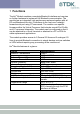
1 Functions The blu2i Module contains a complete Bluetooth interface and requires no further hardware to implement full Bluetooth communication. The module has an integrated, high performance antenna together with all RF and Baseband circuitry, it interfaces to the host over a straight forward serial port using AT commands. The module runs specific firmware within the Virtual Processor that includes a serial Port Profile and AT command interpreter.
2 Application Interface The blu2i Module is equipped with a 40-pin 0.5mm pitch board to board connector that connects to the application platform. Electrical and mechanical characteristics of the board-to-board connector are specified in Chapter 3. • Serial interface (see Section 3.0) • Electrical specification of the interface (see Section 3.1) 2.1 Serial Interface UART_TX, UART_RX, UART_RTS and UART_CTS form a conventional asynchronous serial data port.
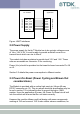
blu2i Module Application /RXD /TXD /RTS /CTS /DTR /DSR /DCD /RING RS232 Interface UART Interface UART_TX UART_RX UART_CTS UART_RTS UART_DTS UART_DTR UART_DCD UART RI Figure: UART interfaces 2.2 Power Supply The power supply for the blu2i Module has to be a single voltage source of Vcc= 3.6V to 6V. It must be able to provide sufficient current in a transmit burst which can rise to 65mA. The module includes regulators to provide local 3.3V and 1.8V.
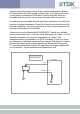
example when the supply voltage to the module experiences a BrownOut (momentary dip in the supply voltage level), or a rapid power cycle i.e. the power is switched off and then on within 1second, there is a possibility that the module can enter an unknown state of operation. It is strongly recommended that the application hardware onto which the module is mounted provides a Power-On-Reset circuit with a Brown-Out detection capability.
2.4 SPI Bus The module is a slave device that uses terminals SPI_MOSI, SPI_MISO, SPI_CLK and SPI_CSB. This interface is used for program firmware update. Note: The designer should be aware that no security protection is built into the hardware or firmware associated with this port, so the terminals should not be permanently connected in a PC application. 2.5 Parallel PIO Port Five lines of programmable bi-directional input/outputs (I/O) are provided. GPIO[1:5] are powered from VCC.
3 Electrical specification of the interface The Hirose DF12C board to board connector on the module is a 40 way double-row receptacle. The pin allocation is as follows: Pin 1 3 5 Signal Analogue 0 Analogue 1 SPI_MISO 7 SPI_CSB 9 SPI_CLK 11 GND 13 RESET 15 GND 17 SPI_MOSI 19 UART_CTS 21 UART_TX 23 UART_RTS 25 UART_RX 27 VCC_3V3 29 VCC_5V 31 33 35 37 39 N/C N/C N/C N/C VCC_1V8 Description 1.8v Max 1.
Notes: • UART_RX, UART_TX, UART_CTS, UART_RTS, UART_RI, UART_DCD and UART_DSR are all 3.3v level logic. For example, when RX and TX are idle they will be sitting at 3.3V. Conversely for handshaking pins CTS, RTS, RI, DCD, DSR a 0v is treated as an assertion. • Pin 6 (UART_RI) is active low. It is normally 3.3v. When a remote device initiates a connection, this pin goes low. This means that when this pin is converted to RS232 voltage levels it will have the correct voltage level for assertion.
3.1 Electric Characteristics Function Power Supply RS232 Interface External Power Supply SPI Bus Signal Name Vcc Pin No 29 I/O I GND 11, 15, 18, 30, 36, 38 UART_TX 21 O UART_RX 25 I UART_CTS 19 I UART_RTS 23 O UART_DSR 10 I UART_DTR 12 O UART_RI 6 I or O UART_DCD 8 I or O VCC_1V8 39 O VCC_3V3 SPI_MOSI 27 17 O I SPI_MISO 5 O SPI_CSB 7 I SPI_CLK 9 I Signal level 3.6V to 6V Comments Ityp = 50mA 6 Ground terminals to be attached in parallel 11 of 36 VOLmax=0.
PCM Interface PCM_CLK 20 I or O PCM_IN 22 I PCM_SYNC 24 I or O PCM_OUT 26 O BC02 USB D- 32 I 34 I GPIO BC02 USB D+ GPIO 1 - 5 2,4,12, 14,16 I or O Analog I/O AIO_0, AIO_1 1, 3 I/O Reset RESET 13 I Reserved 12 of 36 VIHmin=2.10V VIHmax=3.7V O/P : VOLmax=0.2V VOHmin=2.8V I/P : VILmax=0.8V VIHmin=2.10V VIHmax=3.7V VILmax=0.8V VIHmin=2.10V VIHmax=3.7V O/P : VOLmax=0.2V VOHmin=2.8V I/P : VILmax=0.8V VIHmin=2.10V VIHmax=3.7V VOLmax=0.2V VOHmin=2.8V VILmax =0.3vdd_pads VIHmin =0.
4 Physical Characteristics 4.
4.2 Mounting the blu2i Module onto the application platform There are many ways to properly install the Module in a host device. An efficient approach is to mount the PCB to a frame, plate, rack or chassis. Fasteners can be M1.8 or M2 screws plus suitable washers, circuit board spacers, or customized screws, clamps, or brackets in 2.2mm diameter holes. Note that care should be taken to ensure the head of the fixing does not interfere with the circuit. Nylon fixings are recommended.
Mating headers from Hirose are available in different stacking heights. Details are available at: http://www.hirose.co.jp/cat2002e/500/e53700036.pdf Item Headers DF12 series Part number DF12(3.5)-40DP0.5V(81) DF12(4.0)-40DP0.5V(81) DF12(5.0)-40DP0.5V(81) Stacking height 3.5mm 4.0mm 5.0mm HRS number CL537-0032-4** CL537-0057-5** CL537-0157-0** Note: The headers listed above are without boss and metal fitting.
5 Electrical and radio characteristics 5.1 Absolute Maximum ratings Absolute maximum ratings for supply voltage and voltages on digital and analog pins of the module are listed below. Exceeding these values will cause permanent damage. Minimum 0mA -0.3V 3.3V Peak current of power supply Voltage at digital pins Voltage at POWER pin Maximum 100mA 3.7V 7V 5.2 Operating temperatures Minimum -20°C Operating temperature Typical 25°C Maximum +75°C 5.
being transferred and when data is being transferred at the maximum rate possible. The operating mode can best be described by stating the AT commands required to enter that mode. In addition, there are certain S Registers which have a direct impact on power consumption, which are described next. The blu2i Module has 2 LEDs which can be configured to display connection status.
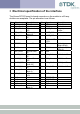
Current per LED Idle Mode, S512=1 Wait for Connection Or Discoverable Mode, AT+BTP S508=S510=640, S509=S511=320 Wait for Connection Or Discoverable Mode, AT+BTP S508=S510=1000, S509=S511=11 Inquiring Mode, AT+BTI Connecting Mode (ATDxxx) Connected as Master Mode (No Data Transfer) Sniff NOT activated Connected as Master Mode (Max Data Transfer) Sniff NOT activated Connected as Slave Mode (No Data Transfer) Connected as Slave Mode (No Data Transfer) Sniff Enabled (AT&F1 setting) 9600 3.20 5.
It is possible to reduce the duty cycle down to as low as 0.5% at the expense of response time. The response time can be specified via S Registers 508 and 510 for page and inquiry respectively, where the worst case response time can be as high as 2.5 seconds. Then the duty cycle can be varied by changing the value of S Registers 509 and 511 appropriately.
contacted during N-M slots, and so can switch its power hungry circuitry off. The specification goes further by also specifying a third parameter called ‘timeout’ (T) which specifies ‘extra’ timeslots that the slave will agree to listen for after receiving a valid data packet. Put another way, if a data packet is received by the slave, then it knows that it MUST carry on listening for at least T more slots. If within that T slot time period another data packet is received, then the timer is restarted.
5.5 RF performance 5.5.1Transmit Power Conducted Transmit Power: Antenna Gain: Effective Transmit Power: minimum: 1mW (0dBm) maximum: 4mW (6dBm) Power class 1 +2dBi typical. min: 2dBm max:8dBm 5.5.
case data though-put with and without the AT command processing. Distances are measured in free space between 2 blu2i Modules. Data Transfer Rate / Distance 800 700 Data Transfer Rate (kbps) 600 500 RF data rate Serial port data rate 400 300 200 100 0 10m 50m 100m 150m 200m 250m 300m Distance (meters) 5.5.
5.
6 RS232 Modem Signals Just as a telephony modem has control and status lines, the blu2i Module also provides for 6 control and status lines as per the table below. The direction column is as seen from the modules viewpoint.
specified in S Register 519 then the connection is dropped as if an ATH command was received. 2 PIO2 (RI), is normally deasserted. When an incoming connection is detected it will be asserted, until the connection is either answered or rejected using ATA and ATH respectively. See S Registers 552 & 553 for more details 3 PIO3 (DCD) will be deasserted when the device is in the unconnected state. Asserted when a connection is active. See S Registers 552 and 553 for more details.
Future enhancement may allow the BREAK signal to be used to map to GPIO which with appropriate external hardware may allow for a BREAK to be reproduced on the TX line. 6.3 Reset The module can be reset by the host without the need of any I/O using a BREAK signal. The module has been configured to reset when the RX line detects a break condition for durations greater than 100 milliseconds.
7 Pure Cable Replacement Mode 7.1 Data Cable The module has the capability of being preset into a pure 5-wire data cable replacement mode. The 5 wires being RX, TX, CTS, RTS and GND. This mode requires no changes to a host application since the Bluetooth connection is automatically set up on power up and will retry when the connection drops. By implication, two devices are needed to replace a cable. One device is pre-configured to always be a master and the other, a slave.
Where is optional. If it is not specified, then the slave unit will accept connections from any device. If specified then only connections from the device specified will be accepted. If it is desired that the slave unit not be discoverable (the master is by default not discoverable), then the configuration commands are, AT&F ATS512=3 ATS0=-1 AT&W AT+BTR Where is optional. If it is not specified, then the slave unit will accept connections from any device.
ATS504=1 ATS530=2000 ATS532=1 AT&W AT+BTR And the slave is configured by, AT&F ATS512=4 ATS0=-1 AT&W AT+BTR 7.3 Modem Control and Status Signals A serial port has DTR, DSR, RTS, CTS, DCD and RI control lines. RTS and CTS are locally controlled to prevent local buffer overflow. However the status of DTR, DRS, DCD and RI can be exchanged with the remote peer device.
8 Getting Started This section describes how to quickly make your first Bluetooth connection based on the following combinations of Bluetooth hardware:1. Two blu2i Modules. 2. One blu2i Module and a Bluetooth Enabled PC using TDK’s Go Blue USB Adaptor or PC Card. Note: The following examples assume that a PC is used to control the blu2i Module using a Terminal Emulation application. 8.1.
Now typing characters on one terminal emulator will result in them being displayed on the other terminal emulator, proving wireless communications. 8.1.2One blu2i Module and Bluetooth PC using TDK’s USB Adaptor or PC Card Assuming your PC has 1 serial port (COM1) with a blu2i Module attached and the latest Windows Bluetooth stack from TDK installed. Also confirm that the TDK Go Blue USB Adaptor or PC Card is connected to your PC and that it is functional.
8.2 Factory Default Mode The module is capable of operating at a very wide range of baud rates and S Registers 520 and 521 allow the baud rate to be set very easily. The baud rate clock generator in the module is more versatile that that available in a standard 16550 UART commonly available in PCs. In fact, as long as the equation BAUDRATE * 0.004096 produces an integer value, then there will be 0% error in clocking for that baud rate.
Baud rate: 300 to 921600 Parity: None, Odd, Even Data Bits: 7 or 8 Stop Bits: 1 or 2 Handshaking: None or CTS/RTS The unique benefits of using TDK Terminal are: • • • • Status of DSR, CTS, DCD and RI are continuously displayed DTR can be directly controlled via a check box RTS can be directly controlled BREAK signals can be sent Also, there is a “Data Transfer Test” mode allowing data to be sent as fast as the handshaking will permit.
Appendix A Europe – EU Declaration of Conformity DECLARATION OF CONFORMITY In accordance with Annex IV of the EU directive 1999/5/EC Notified Body consulted: ID-Number of Notified Body: Phoenix Test-Lab 0700 declare under our responsibility that the blu2i Module complies with the appropriate essential requirements of the Article 3 of the R&TTE and the other relevant provisions, when used for its intended purpose.
Appendix B ESD (Electrostatic Discharge) If your TDK Bluetooth device is affected by ESD, it is recommended that you restart any Bluetooth processes that were active at the time. Additional Statement TDK SYSTEMS' BLUETOOTH PRODUCTS ARE NOT AUTHORISED FOR USE AS CRITICAL COMPONENTS IN LIFE SUPPORT DEVICES OR SYSTEMS WITHOUT THE EXPRESS WRITTEN APPROVAL OF THE MANAGING DIRECTOR OF TDK SYSTEMS EUROPE.
Warranty TDK warrants that its products shall conform to TDK’s published specifications and remain free from defects in materials and workmanship under normal, proper and intended use for a period of two (2) years from date of purchase, provided that proof of purchase be furnished with any returned equipment.