
Data Sheet

DENSEI-LAMBDA
CA757-01-01A
ITEMS
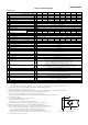
1 Nominal Output Voltage V 3.3 5 12 15 24 36 48 60
2 Maximum Output Current ( Peak Output Current ) ( * 1 ) A 120 120 53 43 27 (31) 18 13 (15) 10
3
Maximum Output Power ( Peak Output Power ) ( * 1 )
W 396 600 636 645 648 (744) 648 624 (720) 600
4 Efficiency (Typ) (115/230VAC) ( * 2 ) % 70/72 75/77 79 / 82 79 / 82 81/84 82 / 84 82 / 84 82 / 84
5 Input Voltage Range ( * 3 )
6 Input Current (Typ) (115/230VAC) ( * 2 ) A 5.0 /2.5
7 Inrush Current (Typ) ( * 4 )
8 PFHC
9 Power Factor (Typ) (115/230VAC) ( * 2 )
10 Output Voltage Range V 2.64~3.96 4.0~6.0 9.6~14.4 12.0~19.5 19.2~28.8 28.8~43.2 38.4~56.0 48.0~66.0
11 0?Ta?74°C mV 120 120 150 150 150 200 200 200
-20?Ta?0°C mV 160 160 180 180 180 240 240 240
12 Line Regulation ( * 5, 6 ) mV 20 20 48 60 96 144 192 240
13 Load Regulation ( * 5, 7 ) mV 30 30 72 90 144 216 288 360
14 Temperature Coefficient
15 Over Current Protection ( * 8 ) A 126~ 126~ 55.7~ 45.1~ 31.3~ 18.9~ 15.2~ 10.5~
16 Over Voltage Protection ( * 9 ) V 4.12~5.61 6.25~7.25 15.0~17.4 20.2~23.4 30.0~34.8 45.0~52.2 58.5~68.2 69.0~81.0
17 Hold-Up Time (Typ) (115/230VAC) ( * 2 )
18 Leakage current ( * 10 )
19 Remote Sensing
20 Remote ON/OFF control
21 Monitoring Signal
22 Parallel Operation
23 Series Operation
24 Operating Temperature
( * 11 )
25 Operating Humidity
26 Storage Temperature
27 Storage Humidity
28 Cooling
29 Withstand Voltage
30 Isolation Resistance
31 Vibration ( * 12 )
32 Shock (In package)
33 Safety
( * 13 )
34 Line Dip
35 EMI
36 Immunity
37 Weight (Typ)
38 Dimension (W x H x D) mm
* Read instruction manual carefully , before using the power supply unit.
= NOTES=
* 1: ( ): Peak Output Current is possible at 170~265VAC input range , operating period at Peak Output Current is less than 10sec, duty less than 35% .
Average output power and current is less than Maximum Output Power and Maximum Output Current.
* 2 : At Maximum Output Power, nominal input voltage, Ta = 25°C.
* 3 : For cases where conformance to various safety specs ( UL, CSA, EN ) are required, to be described as 100 - 240VAC, 50 / 60Hz on name plate.
* 4 : First/second inrush current, not applicable for the in-rush current to Noise Filter for less than 0.2ms.
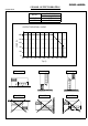
* 5 : Please refer to Fig A for measurement of line & load regulation, ripple and noise voltage.
Ripple & noise are measured at 20MHz by using a twisted pair of load wires terminated with a 0.1uF and 47uF capacitor.
* 6 : 85 - 265VAC, constant load.
* 7 : No load - Full load ( Maximum power ), constant input voltage.
* 8 : Constant current limit with automatic recovery.
Avoid to operate at overload or dead short for more than 30 seconds.
* 9 : OVP circuit will shutdown output, manual reset (Remote ON/OFF control reset or Re-power on).
* 10 :
Measured by each measuring method of UL, CSA, EN and DENAN (at 60Hz), Ta=25°C.
* 11:
Refer to Output Derating Curve (CA757-01-02_) for details of output derating versus ambient temperature.
- Load (%) is percent of Maximum Output Power and Maximum Output Current ( Item 2 and 3).
Do not exceed derating of Maximum Output Power and Maximum Output Current.
- 100% load start up at -40°C is possible. However, it may not fulfil all the specifications.
* 12:
Category 4 exposure levels: Trunk transportation over U.S. highways, Composite two-wheeled trailer.
* 13: As for DENAN, designed to meet at 100VAC.
100% load start up at -40°C
Less than 0.75mA . 0.3mA (Typ) at 115VAC / 0.5mA (Typ) at 230VAC .
Output - FG : 500VAC (100mA) (60V model: 651VAC, 130mA)
Possible
Output - CNT/ALM/AUX: More than 50MΩ (100VDC) at Ta=25°C and 70%RH
20 ~ 90 %RH (No dewdrop)
- 40 ~ +85°C
10 ~ 95%RH (No dewdrop)
Forced air by build-in fan
Designed to meet MIL-STD-810F 516.5 Procedure I,VI
Designed to meet DENAN, EN61010-1
Designed to meet MIL-STD-810F 514.5 Category 4, 10
Ripple and Noise (115/230VAC)
( * 5 )
1.6kg
Input - Output : 3.0kVAC (20mA), Input - FG : 2.0kVAC (20mA)
Output - CNT/ALM/AUX : 100VAC (100mA) for 1min.
Input - FG, Input - Output and Output - FG: More than 50MΩ (500VDC)
Possible
Possible
- 20 ~ + 74 °C (-20°C ~ +50°C: 100%, +74°C: 50%)
Designed to meet SEMI-F47 (200VAC line only)
120 x 61 x 190 (Refer to Outline Drawing)
Designed to meet UL60950-1, CSA60950-1, EN60950-1, EN50178
Designed to meet VCCI-B, FCC-B, EN55011/EN55022-B
Designed to meet EN61000-4-2 (Level 2,3), -3 (Level 3), -4 (Level 3),
-5 (Level 3,4), -6 (Level 3), -8 (Level 4), -11
Possible
ALM ( Open Collector Output )
Designed to meet IEC61000-3-2
0.98/0.95
Less than 0.02%/°C
20ms
20A/40A at 115VAC, 40A/40A at 230VAC, Ta=25°C (first inrush/second inrush)
85 ~ 265VAC (47-63Hz) or 120 ~ 350VDC
SWS600L-15 SWS600L-24
SWS600L SPECIFICATIONS
7.1 / 3.6
SWS600L-3 SWS600L-60SWS600L-36 SWS600-48SWS600L-5 SWS600L-12
MODEL
Output Terminal
Measurement point for Vo Line/Load Regulation
Measurement point for Ripple and Noise
47µ 0.1µ
150mm
Fig.A
A
-V
+V