SWS1000L INDEX PAGE 1. Calculated values of MTBF ……………………………………………………………… R-1 2. Component derating ………………………………………………………………………… R-2 3. Main components temperature rise ΔT list ……………………………………………… R-7 4. Electrolytic capacitor lifetime ……………………………………………………………… R-9 5. Abnormal test ……………………………………………………………………………… R-10 6. Vibration & shock test ..……………………. …………………………………………… R-13 7. Noise simulate test ……………………………………………………………………… R-19 8. Thermal shock test ………………………………………………………………………. R-20 9.
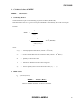
SWS1000L 1. Calculated values of MTBF MODEL : SWS1000L-5 1. Calculating Method Calculated based on part count reliability projection of JEITA (RCR-9102).
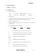
SWS1000L 2. Component derating MODEL : SWS1000L-5 (1) Calculating method (a) Measuring Conditions Input : 115 , 230VAC Ambient temperature : 50°C Output : 5V 200A (100%) Mounting method : Mounting A (b) Semiconductors Compared with maximum junction temperature and actual one which is calculated based on case temperature, power dissipation and thermal impedance. (c) IC, Resistors, Capacitors, etc. Ambient temperature, operating condition, power dissipation and so on are within derating criteria.
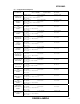
SWS1000L (2) Component Derating List Location No. Q1, Q2, Q4 F20W60C3-7100 SHINDENGEN Q3, Q5 2SK3907(Q) TOSHIBA Vin = 115VAC Load = 100% Tchmax = 150°C, θ ch-c = 1.66°C/W, Pch = 8.14W, Δ Tc = 36.8°C, Tch = Tc + ((θ ch-c) × Pch) = 100.31°C D.F. = 66.9% Tchmax = 150°C, θ ch-c = 0.833°C/W, Pch = 22.39W, Δ Tc = 36.9°C, Tch = Tc + ((θ ch-c) × Pch) = 105.55°C D.F. = 70.4% Tjmax = 125°C, θ j-a = 666.67°C/W, Q401 2SC2712-Y(TE85L,F) TOSHIBA Pc = 0.016W, Δ Ta = 25.5°C, Tj = Ta + ((θ j-a) × Pc) = 86.17°C D.F.
SWS1000L Location No. SR1 SMG16C60 SANREX A1 TA7805S(Q) TOSHIBA A102 FA5502M-H1-TE1 FUJI-ELEC. A203 M51995AFP CF0J RENESAS A401 MIP2E3DMUL MATSUSHITA A402 TA58M12F TOSHIBA PC404-A PS2581L2-E3(D)-A NEC PC404-B PS2581L2-E3(D)-A NEC Vin = 115VAC Load = 100% Tjmax = 125°C, θ j-c = 1.4°C/W Pd = 4.83W, Δ Tc = 34.0°C, Tj = Tc + ((θ j-c) × Pd) = 90.76°C D.F. = 72.6% Tjmax = 150°C, Pc = 1.62W, Tj = Tc + ((θ j-c) D.F. = 68.0% Tjmax = 150°C, Pd = 0.08W, Tj = Ta + ((θ j-a) D.F. = 59.6% Tjmax = 150°C, Pd = 0.
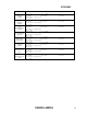
SWS1000L (2) Component Derating List Location No. Q1, Q2, Q4 F20W60C3-7100 SHINDENGEN Q3, Q5 2SK3907(Q) TOSHIBA Q401 2SC2712-Y(TE85L,F) TOSHIBA Q405 2SA1213-Y(TE12L,CF) TOSHIBA D1, D12 D25XB60-7000 SHINDENGEN D2, D3 YG902C3R FUJI-ELEC. D4, D5 YG902C3R FUJI-ELEC.
SWS1000L Location No. SR1 SMG16C60 SANREX A1 TA7805S(Q) TOSHIBA A102 FA5502M-H1-TE1 FUJI-ELEC. A203 M51995AFP CF0J RENESAS A401 MIP2E3DMUL MATSUSHITA A402 TA58M12F TOSHIBA PC404-A PS2581L2-E3(D)-A NEC PC404-B PS2581L2-E3(D)-A NEC Vin = 230VAC Load = 100% Tjmax = 125°C, θj-c = 1.4°C/W Pd = 4.83W, Δ Tc = 25.1°C, Tj = Tc + ((θ j-c) × Pd) = 81.86°C D.F. = 65.5% Tjmax = 150°C, θ j-c = 6.25°C/W, Pc = 1.62W, Δ Tc = 38.8°C, Tj = Tc + ((θ j-c) × Pc) = 98.93°C D.F. = 66.0% Tjmax = 150°C, θ j-a = 192.
SWS1000L 3.
SWS1000L MODEL : SWS1000L-5 Condition: (A) Standard Mounting (Mounting Method (A)) Input Voltage (VAC) 230 Output Voltage (VDC) 5 Output Current (A) 200 ΔΤ Temperature rise (°C) Output Derating Io=100% (Ta =50°C) Io=50% (Ta =74°C) Location No Parts Name Mounting (A) Mounting (A) L1 L4 L7 L2, L8 L17 L39 T1 T2 T3 T4 D1, D12 D2, D3 D4, D5 D6-D11, D13 SR1 Q1, Q2, Q4 Q3, Q5 A102 A203 A401 C10, C11 C15-C18 C21 C22 C23 C24 C26 C28 C19, C29 BALUN COIL BALUN COIL CHOKE COIL CHOKE COIL CHOKE COIL CHOKE
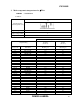
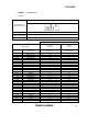
SWS1000L 4. Electrolytic capacitor lifetime MODEL: SWS1000L-5 Conditions: Mounting A INPUT Ta = 25°C = 40°C = 50°C = 74°C OUTPUT Vin = 115VAC 20 40 50 60 80 100 25°C 10.0 10.0 10.0 10.0 10.0 9.8 40°C 8.5 7.7 7.5 7.2 6.2 3.9 50°C 4.4 4.4 4.2 4.0 3.3 1.7 74°C 1.2 1.1 1.
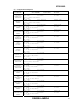
SWS1000L 5. Abnormal test Model: SWS1000L-5 (1) Test Condition and Circuit Input Voltage: 230Vac Output: 5V 200A Ta : 25°C , 70%RH (2) Test Results (Da: Damaged) No.
SWS1000L No.
SWS1000L No. Test Position L O C A T I O N 19 T4 20 PC1 21 PC402 22 PC404 23 PC405 Test Mode P T O E I S N T T S H O R T 1-2 3-4 5-7 9 - 10 1 3 5 9 1-2 5-6 1-2 3-4 1-2 3-4 1 2 3 4 1-2 3-4 Ο Ο Ο Ο O P E N Test Results 1 F I R E 2 S M O K E 3 B U R S T 4 S M E L L 5 R E D H O T 6 D A M A G E 7 F U S E B L O W 8 O . C . P . 9 O . V . P .
SWS1000L 6. MIL-STD-810F VIBRATION & SHOCK TEST (1) Truck transportation over U.S. highways vibration test (MIL-STD-810F 514.5 Category 4- Truck/trailer/tracked-restrained cargo) 1. Purpose Test based on [MIL-STD-810F 514.5 Category 4-Truck/trailer/tracked-restrained cargo-Truck transportation over U.S. highways] 2. Test method Unit was taken directly from production line.Unit was compliant with production standards. The performance of vibration test machine is confirmed before vibration test.
SWS1000L (2) Composite two-wheeled trailer vibration test (MIL-STD-810F 514.5 Category 4- Truck/trailer/tracked-restrained cargo) 1. Purpose Test based on [MIL-STD-810F 514.5 Category 4-Truck/trailer/tracked-restrained cargo-Mission/field transportation Two-wheeled trailer] 2. Test method Unit was taken directly from production line.Unit was compliant with production standards. The performance of vibration test machine is confirmed before vibration test.
SWS1000L (3) Shipboard random vibration test (MIL-STD-810F 514.5 Category 10- Ship-surface ship) 1. Purpose Test based on [MIL-STD-810F 514.5 Category 10-Ship-surface ship]. 2. Test method Unit was taken directly from production line.Unit was compliant with production standards. The performance of vibration test machine is confirmed before vibration test. Unit is tested in random vibration conditions based on [MIL-STD-810F_figure 514.5C-15] Acceleration spectral density [g/Hz ] Figure 514.
SWS1000L (4) Functional shock test (MIL-STD-810F 516.5 Procedure I) 1. Purpose Test based on [MIL-STD-810F 516.5 Procedure I - Functional shock]. 2. Test method Unit was taken directly from production line.Unit was compliant with production standards. The performance of vibration test machine is confirmed before vibration test. Unit is operating during shock test. Min.peak value (g's) Duration Qty.
SWS1000L (5) Bench handing test (MIL-STD-810F 516.5 Procedure VI) 1. Purpose Test based on [MIL-STD-810F 516.5 Procedure VI - Bench handing]. 2. Test method Unit was taken directly from production line.Unit was compliant with production standards. Use test bench with thickness of at least 4.25cm. With unit switched off. Raise until the chassis forms an angle of 45° with the bench top. Drop unit on each face on which unit could be placed practically. In the above test method, repeat drop 4 times in total.
SWS1000L (6) APPENDIX APPENDIX A : List of equipment used EQUIPMENT USED MANUFACTURER MODEL NO. TRUE RMS MULTIMETER FLUKE 89 VI DIGITAL POWER METER YOKOGAWA ELECT.
SWS1000L 7. Noise simulate test MODEL : SWS1000L-5 (1) Test circuit and equipment Simulator : ENS-24X SANKI E.IND • Input voltage : 115, 230VAC Noise level : 0V~2.0kV • Output voltage : Rated Phase shift : 0° ~ 360° • Output current : 0%, 100% Polarity : +,- • Ambient temperature : 25°C Mode : Normal, Common • Pulse width 50ns ~ 1000ns Trigger select : Line (2) Test conditions : (3) Acceptable conditions 1. Not to be broken. 2. Not to be shut down output. 3.
SWS1000L 8. Thermal shock test MODEL : SWS1000L-5 (1) Equipment used THERMAL SHOCK CHAMBER TSV-40 (TABAI ESPEC CORP.) (2) The number of D.U.T.(Device Under Test) 1 unit (3) Test Conditions • • • • Ambient temperature Test time Test cycle Not operating 1Cycle : -40°C ~ 85°C : Refer to drawing : 100 cycles 85°C 30min -40°C (4) Test Method 30min Before testing, check if there is no abnormal output, then put the D.U.T. in testing chamber, and test it according to the above cycle.
SWS1000L 9. Fan life expectancy MODEL: SWS1000L (1) Part name 9A0612G4D041 (SANYO DENKI CO.) Life expectancy The data shows fan life expectancy for fan only by manufacture (90% survival rate). Fig1 shows measuring point of ambient temperature. 10 Life expectancy (years) (2) 1 0 50 100 Ambient temperature (℃) Measuring Point Air Flow P.S. 50mm Fig1.