
Data Sheet


PXC-M06 (W) Series
2
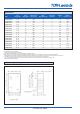
Model Selector
Input Output Output Current Output
(7)
InputCurrent Efciency Maximum
Model Voltage(VDC) Voltage(VDC) FullLoad(mA) Ripple&Noise(mV) NoLoadmA %
(2)
Capacitive Load
(2)
PXC-M06-24WS3P3 9 ~ 36 3.3 1800 30 6 83 2100
PXC-M06-24WS05 9 ~ 36 5 1200 30 6 86 1500
PXC-M06-24WS12 9 ~ 36 12 500 40 6 89 260
PXC-M06-24WS15 9 ~ 36 15 400 40 6 89 210
PXC-M06-24WS24 9 ~ 36 24 250 50 6 88.5 75
PXC-M06-24WD05 9 ~ 36 ±5 ±600 30 6 85 ± 860
PXC-M06-24WD12 9 ~ 36 ±12 ±250 40 6 88.5 ± 150
PXC-M06-24WD15 9 ~ 36 ±15 ±200 40 6 88.5 ± 110
PXC-M06-48WS3P3 18 ~ 75 3.3 1800 30 4 82.5 2100
PXC-M06-48WS05 18 ~ 75 5 1200 30 4 86.5 1500
PXC-M06-48WS12 18 ~ 75 12 500 40 4 88 260
PXC-M06-48WS15 18 ~ 75 15 400 40 4 88.5 210
PXC-M06-48WS24 18 ~ 75 24 250 50 4 88 75
PXC-M06-48WD05 18 ~ 75 ±5 ±600 30 4 85 ± 860
PXC-M06-48WD12 18 ~ 75 ±12 ±250 40 4 88 ± 150
PXC-M06-48WD15 18 ~ 75 ±15 ±200 40 4 87 ± 110
Notes
1.NotavailableforAtypepinconguration
2. Typical value at nominal input voltage and full load.
3. MIL-HDBK-217F Notice2 @Ta=25 ºC, Full load (Ground Benign, controlled environment).
4.BuiltinClassAlter.ClassBcanbeachievedwiththeadditionofexterenalcomponentsforfurtherinformationcontactyourlocalTDK-Lambdasalesofce
5. Meeting EN61000-4-4 and 61000-4-5 requires and additional input electrolytic capacitor: 5V input -1000µF/25V, 12V & 24V input - 470µF/50V and 48V input - 330µF/100V
6. The ON/OFF control pin voltage is referenced to -Vin.The ctrl pin input current is <1mA.Remote off input current is typically 2.5mA
7. For R & N, measure the 24V output with a 4.7µF/50V X7R MLCC. All other outputs use a 10µF25V X7R MLCC. Nominal input, full load at +25°C
8. Reinforced insulation 8mm at 250VAC
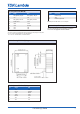
Outline Drawing PXC-M06 (W)
MPP06
MPP06W
Series
P-DUKE Technology Co., Ltd.
www.pduke.com
2018.03.23 Page 6
RECOMMENDED PAD LAYOUT
A TYPE
B TYPE
All dimensions in inch[mm]
Pad size(lead free recommended)
Through hole 1.11.12.13.15.23.24: Φ0.035[0.90]
Top view pad 1.11.12.13.15.23.24: Φ0.044[1.13]
Bottom view pad 1.11.12.13.15.23.24: Φ0.071[1.80]
All dimensions in inch[mm]
Pad size(lead free recommended)
Through hole 1.2.10.11.14.16.22.23: Φ0.035[0.90]
Top view pad 1.2.10.11.14.16.22.23: Φ0.044[1.13]
Bottom view pad 1.2.10.11.14.16.22.23: Φ0.071[1.80]
MECHANICAL DRAWING(CONTINUED)
B TYPE
PIN CONNECTION
PIN
SINGLE DUAL
1 Ctrl (Option) / No pin* Ctrl (Option) / No pin*
2 - Vin - Vin
10
Trim (Option) / No pin* Trim (Option) / No pin*
11 No pin / NC ** -Vout
14
+Vout +Vout
16
-Vout Common
22
+Vin +Vin
23
+Vin +Vin
* If don’t choose Ctrl or Trim option, there is
no pin on the corresponding pin number.
**
Pin 11 is “No pin” for
MPP06-□□S□□□B-T
MPP06-□□S□□□B-PT
Pin 11 is “NC” for
MPP06-□□S□□□B
MPP06-□□S□□□B-P
1. All dimensions in inch [mm]
2. Tolerance :x.xx±0.02 [x.x±0.5]
x.xxx±0.01 [x.xx±0.25]
3. Pin pitch tolerance ±0.01 [0.25]
4. Pin dimension tolerance ±0.004[0.10]