
Data Sheet

GWS500 Series
2
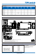
Model Selector
Adjust
2
Max Peak Curr.
1
Load Line Ripple Efciency
Model Voltage Range Current <10s Reg. Reg. Noise (typ)%
(V) (V) (A) (A) (mV) (mV) (mV) (230VAC)
GWS500-5 5V 4.5 - 5.5 80 - 50 25 150 84
GWS500-7.5 7.5V 6.75 - 8.25 67.2 - 70 35 150 87
GWS500-12 12V 10.8 - 13.2 42 - 96 48 150 89
GWS500-24 24V 22 - 28.8 21 25.0 192 96 150 90
GWS500-36 36V 32 - 40 14 16.7 288 144 200 90
GWS500-48 48V 42 - 57.6 10.5 - 384 192 300 90
Notes: (1) Peak current 10seconds. 35% duty cycle max. (2) By trim pot provided. Wider adjustment is possible by external voltage control. Seeinstructionmanualfordetails.
Outline Drawing GWS500 Series
NOTES: A. Model name, Input voltage range, Nominal output voltage, Maximum output current & country of
manufacture are shown in accordance with the specication.
B. M4 tapped, embossed & countersunk holes (B) for customer chassis mounting.
Screws must not protrude into power supply by more than 5mm
Mounting Options GWS500 Output Derating according to the Mounting Directions
Mounting Method
Output Derating according to the Mounting Directions
Recommended standard mounting is Method (A).
Method (B) is also possible.
12
TDK-Lambda
GWS
500
Series
INSTRUCTION MANUAL
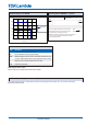
6. Mounting Directions
6-1. Output Derating according to the Mounting Directions
Recommended standard mounting is Method ( A ). Method ( B ) is also possible.
Refer to the Derating below.
(A) Standard Mounting (B)
6-2. Output Derating
For /L and /P option, the system is forced air cooling with external airflow of at least 15cfm and air blowing out from the
opposite side of the input/output connectors.
70
50
Airflow
(≥ 15 cfm)
OUTPUT DERATING CURVE
0
20
40
60
80
100
120
-25 0 25 50 75 100
Ta (
o
C)
LOAD (%)
MOUNTING
A,B
70
50
(A) Standard Mounting
12
TDK-Lambda
GWS
500
Series
INSTRUCTION MANUAL
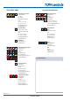
6. Mounting Directions
6-1. Output Derating according to the Mounting Directions
Recommended standard mounting is Method ( A ). Method ( B ) is also possible.
Refer to the Derating below.
(A) Standard Mounting (B)
6-2. Output Derating
For /L and /P option, the system is forced air cooling with external airflow of at least 15cfm and air blowing out from the
opposite side of the input/output connectors.
70
50
Airflow
(≥ 15 cfm)
OUTPUT DERATING CURVE
0
20
40
60
80
100
120
-25 0 25 50 75 100
Ta (
o
C)
LOAD (%)
MOUNTING
A,B
70
50
(B)