
User manual


1
TDK-Lambda
GWS 2
50
Series
INSTRUCTION MANUAL
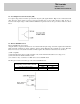
1. Model name identification method
GWS
GWSGWS
GWS
250
250250
250
–
––
–
12
1212
12
/
//
/
2. Terminal Explanation
2-1. Front Panel Explanation
(1) L : Input terminal Live line (Fuse in line)
(2) N : Input terminal Neutral line
(3) FG
: Frame Ground
(4) - V : - Output terminal
(5) +V : + Output terminal
(6) Output monitoring indicator (Green LED : ON)
(7) V.ADJ : Output voltage adjustable trimmer
(The output voltage rises when the trimmer is turned clockwise.)
(8) CN1: DC_OK, 5VSB, Remote On/Off and PV signals (Refer to 2.2)
(*1)
blank: Standard type
/P: Power up to 350W with system airflow of
20cfm minimum and air blowing in from
opposite side of input/output connectors
/BAT: Battery charging for 24V (21~29V/8.8A)
& 48V (42~58V/4.4A) only
/T: OTP autorecovery after unit cools down
/RL: Remote ON/OFF reverse logic (Active High)
Option (*1)
Rated Output Voltage
Output Power type
Series name