
User manual


13
1. Serial Data output
The serial data is sent to the data output pin (pin 10)
twice every A/D conversion cycle. The data format
complies with JIS 7BIT transmission code with a baud
rate of 2400. The host can use the RS232 interface to
read the data. A single data packet allows a start bit
(always 0), 7 data bits, an odd parity check bit, and a
stop bit (always 1). The high and low voltage levels
correspond to +V and -3V respectively. The serial output
remains at 1 (high) when it is inactive. Hence the start
bit (0) could be used as the triggering signal to begin
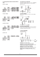
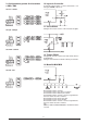
the reading process. The following figure shows the
data format of a single packet. The LSB is sent first
and the MSB is sent last.
One data block consists of 11 packets, or 110 bits. The
following figure shows the format of a data block. The
range packet indicates the full scale range of the meter.
Digit 3 through to digit 0 represent the digits on the
meters display. The function packet indicates the
measurement mode of the meter. Status, option 1, and
option 2 give the status of the meter. CR and LF are
delimiters used to separate the blocks.
The meter always outputs the current input value to the
serial port regardless of whether the hold function has
been activated or not. Each block is repeated twice in
one conversion cycle. The detailed data format of each
packet is listed below.
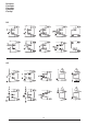
2. Function
This packet indicates the measurement mode of the
meter. The following table summarises the transmitted
code for each mode. Note that the encoding of this
packet is different to the encoding of the FC1 to FC4
switch.
3. Range
This packet indicates the full scale range of the meter.
When the meter is in current mode (A) this packet is
always 0110000 since the full scale range in this mode
is fixed. The following table shows the codes for each
range.
4. Digit 3 to digit 0
Digit 3 is the most significant digit on the LCD panel,
and the digit 0 is the least significant digit. When the
LCD panel shows OL the serial port outputs 4000.
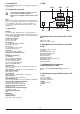
5. Status
The format of this packet is shown below. (The judge
field is not applicable to these units, but will be present
in the data field- it should be disregarded). The sign
field indicates whether the minus sign on the LCD is
ON or OFF. The Batt field indicates if the battery low
condition is true. OL indicates input overflow.
6. Option 1
This packet contains information on special measurement
modes. The format of this packet is shown below. The
three none constant fields are set to "1" when the meter
operates in the corresponding special modes, max and
min. Bit 0 (VAHZ) is not applicable.
0
1
LSB MSB
0 1 0 1 0 1
0 1 0 1 0 1
0 1 0 1 0 1
0 1 0 1
range digit3 digit2
digit1 digit0 function
status option1 option2
CR LF
Code Measurement Mode
0111011 Voltage
0111101 µA Current
0111001 mA Current
0111111 A Current
0111110 ADP0
0111100 ADP1
0111000 ADP2
0111010 ADP3
Code V mA µA
0110000 400.0 mV 40.00 mV 400.0 µA
0110001 4.000 V 400.0 mA 4000 µA
0110010 40.00 V
0110011 400.0 V
0110100 4000 V
0110101
Digit Code
0 110000
1 110001
2 110010
3 110011
4 110100
5 110101
6 110110
7 110111
8 111000
9 111001
0 1 1 Judge Sign BATT OL
Bit 6 Bit 5 Bit 4 Bit 3 Bit 2 Bit 1 Bit 0
0 1 1 Pmax Pmin 0 VAHZ
Bit 6 Bit 5 Bit 4 Bit 3 Bit 2 Bit 1 Bit 0