TDE Instruments GmbH Gewerbestraße 8 D-71144 Steinenbronn Version 2012-01 Tel.: +49(0)7157 20801 Fax: +49(0)7157 20813 Email: info@tde-instruments.de Web: www.tde-instruments.
1. Beschreibung 3 3/4-stelliges digitales Volt- und Ampèremeter Einbauinstrument mit LCD Anzeige, LED Beleuchtung, zusätzlicher 40 Segment Bargraphanzeige, Low Bat Anzeige und RS232 Schnittstelle. Instrument konfigurierbar für AC oder DC Messung. Dieses Instrument hat eine automatische Bereichsumschaltung bei einem Messbereich von 400mV bis 300V, sowie einen wählbaren Eingangsstrommessbereich von 1µA bis 10A. Min. & max. Werte werden abgespeichert und können abgerufen werden.
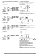
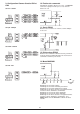
9. Konfiguration Messbereich an CN2 und CN3 10. Steuerungseingänge Gemeinsame Steuerung (Pin 5 und 7) wird auf -3V gehalten. NUR an Pin 8 oder 9 anschliessen. ±0.1mV - 300.0V ±0.1µA - 3999µA 11. RS232 Ausgang Einen Widerstand wie nachstehend gezeigt extern anschliessen. ±0.01mA - 399mA 12. RS232 Trigger Einmal an gemeinsame Steuerung anschließen, um den RS232-Datenstrom zu starten. Zum Stoppen erneut an gemeinsame Steuerung anschliessen. 13. MAX/MIN-Modus ±0.
1. Introduction 4. PCB 3 3/4 digit volt- and ammeter with a 40 segment bargraph indication, LCD display, LED backlight, low bat indication, and RS232 interface. The unit has a fully auto ranging voltage input to 300 V and a selectable 4 scale ammeter up to 10A. Powerded by 5 VDC up to 16 VDC and annunciators for units on display which include min. and max. functions. Unit can be configured for AC or DC measurement. CN2 CN3 ST 3 2.
9. Configuration measuring range at CN2 and CN3 10. Control inputs Control Common (pins 5 and 7) is held at –3V. Do NOT connect to any pin except pins 8 and 9. ±0.1mV - 300.0V ±0.1µA - 3999µA 11. RS232 output Connect a resistor externally as shown below. ±0.01mA - 399mA 12. RS232 trigger Connect to Control common once to start the RS232 data stream. Connect to Control common again to stop. 13. MAX/MIN-Mode ±0.01A - 10A 0 Displaying current value. 1 Displaying current value.
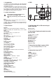
1. Introduction 4. Cartes de circuits imprimés Multimètres analogiques/numériques à sélection automatique de gamme, pour montage sur panneau CN2 2. Instructions de sécurité ! CN3 ST La tension maximale admissible pour tout raccordement sur ce circuit imprimé est de 300V. INLO (0 V) connectée en interne à VSS (0 V) 3 Remarque: La longueur de tout câble mesure (signal) raccordé à cet appareil ne doit pas excéder 30 mètres.
9. Configuration Gamme d'entrée CN2 et CN3 10. Entrées de commande ±0.1mV - 300.0V Commande commune (broches 5 et 7) à -3 V. Ne PAS connecter à quelque broche que ce soit, sauf aux broches 8 et 9. ±0.1µA - 3999µA 11. Sortie RS232 Brancher une résistance en externe, comme indiqué ci-dessous. ±0.01mA - 399mA 12. Déclencheur RS232 Brancher à la commande commune une fois, pour lancer le flux de données RS232. Brancher de nouveau à la commande commune pour arrêter. 13. Mode MAX/MIN ±0.
1. Introducción 4. Circuito impreso Multímetros analógicos/digitales con autocalibración para montaje en panel CN3 CN2 ST 2. Observaciones de seguridad ! El voltaje máximo permitido para cualquier conexión al circuito impreso es 300V. INLO (0 V) va conectadointernamente a VSS (0 V) 3 Nota: Cualquier cable de señal conectado a esta unidad no debe de exceder de 30 metros.
. Configuración campo de medición a CN2 y CN3 10. Entradas de control Control común (clavijas 5 y 7) mantenido a -3V. NO conectar a ninguna clavija, excepto la clavijas 8 y 9. ±0.1mV - 300.0V ±0.1µA - 3999µA 11. Salida RS232 Conectar una resistencia externa como se indica a continuación. ±0.01mA - 399mA 12. Disparo RS232 Conectar a control común una vez para comenzar el tren de datos RS232. Conectar a control común otra vez para detener. 13. Modo MÁX./MÍN. ±0.01A - 10A 0 Indica el valor actual.
1. Introduzione 4. PCB Multimetri digitali/analogici con montaggio a pannello autoranging CN3 CN2 ST 2. Istruzioni di sicurezza ! La tensione massima consentita per una connessione su PCB è di 300V. INLO (0 V) è collegato internamente a VSS (0 V) 3 2 Nota: Ogni cavo di segnale collegato a questo dispusitivo non puo essere piu lungo di 30 metri. Se i cavi di segnale sono installati su un percorso esterno all'edificio, è necessario installare dispositivi di protezione di rete addizionali. 97531 3.
9. Configurazione gamme di misurazione a CN2 e CN3 10. Ingressi di controllo Il controllo comune (pin 5 e 7) viene mantenuto a -3 V. Collegare SOLO ai pin 8 e 9. ±0.1mV - 300.0V 11. Uscita RS232 ±0.1µA - 3999µA Collegare un resistore esterno, come mostrato di seguito. ±0.01mA - 399mA 12. Trigger RS232 Collegare al controllo comune una volta avviato il flusso di dati RS232. Collegare nuovamente al controllo comune per arrestare. 13. Modalità MAX/MIN ±0.01A - 10A 0 Visualizza il valore corrente.
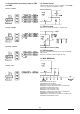
Beispiele Examples Exemples Ejemplos Esempi DC AC 12
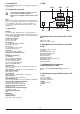
1. Serial Data output 3. Range The serial data is sent to the data output pin (pin 10) twice every A/D conversion cycle. The data format complies with JIS 7BIT transmission code with a baud rate of 2400. The host can use the RS232 interface to read the data. A single data packet allows a start bit (always 0), 7 data bits, an odd parity check bit, and a stop bit (always 1). The high and low voltage levels correspond to +V and -3V respectively. The serial output remains at 1 (high) when it is inactive.
7. Option 2 This packet contains information on the operating mode of the meter. The format of this packet is shown below. The DC field indicates that the meter operates in DC mode, measuring voltage or current. The AC mode indicates that the meter operates in AC mode, measuring voltage or current. The APO field is not applicable. 0 1 1 Bit 6 Bit 5 Bit 4 DC Bit 3 AC AUTO APO Bit 2 Bit 1 Bit 0 8. CR Carriage Return. The transmitted code is 0001101 9. LF Line Feed.
Abmessungen Dimensions Dimensiones Dimensioni PANEL CUT-OUT 33 x 68mm +0.5 / -0.0 (1.3 x 2.68”'94 +.02 / -0.
TDE Instruments GmbH Gewerbestraße 8 D-71144 Steinenbronn Tel.: +49(0)7157 20801 Fax: +49(0)7157 20813 Email: info@tde-instruments.de Web: www.tde-instruments.