
Manual


GB - 1PI_FFA1210_Art0017978_1v2 126301-02
TCS TürControlSysteme AG
Geschwister-Scholl-Straße 7 • D-39307 Genthin
extent
TM
1. General
1.1 Application
Various electric loads such as lamp bulbs, HV halogen
lamps, electronic ballast devices and inductive loads can
be switched with output 1 (channel 1) and output 2
(channel 2) of the radio actuator. The radio actuator is ope-
rated with extent
TM
radio sensors (radio signal).
Before use, the radio sensors must be assigned to the ra-
dio actuator (max. 32 radio sensors). Every radio sensor
can control an unlimited number of radio actuators.
Note: Read through the operating instructions carefully
before putting the device into service.
1.2 Warranty conditions
These operating instructions are an integral part of both the
device and our terms of warranty. They must be handed
over to the user. The technical design of the appliance is
subject to change without prior notification. TCS products
are manufactured and quality-checked with the latest tech-
nology according to applicable national and international re-
gulations. Nevertheless, if a product should exhibit a defect,
TCS warrants to make remedy as follows (regardless of any
claims against the dealer to which the end-user may be en-
titled as a result of the sales transaction):
In the event of a justified and properly-established claim,
TCS shall exercise its prerogative to either repair or re-
place the defective device. Further claims or liability for
consequential damage are explicitly excluded. A justifiable
deficiency is one in which the device exhibits a structural,
manufacturing, or material defect that makes it unusable or
substantially impairs its utility at the time it is turned over to
the end-user. The warranty does not apply to natural wear,
unintended usage, incorrect connection, device tampering
or the effects of external influences. The warranty period
is for 24 months from the date of purchase by the end-user
from a dealer and ends not later than 36 months after the
device’s date of manufacture. German law shall be applica-
ble for the settlement of warranty claims.
1.3 Disposal of the device
The device must be disposed of in compliance with the laws
and standards of the country in which it is operated!
2. Safety
CAUTION! Danger of electrical shock!
The housing contains current-carrying com-
ponents. Contact can lead to personal injury!
All work on the mains network and the de-
vice may only be done by an authorised
electrician.
• Disconnect power supply from the device prior to per-
forming any work on it.
• Secure the device against being powered on again.
• Check that the device is powered off.
• Close the housing securely before applying power.
The following must be observed:
• Prevailing statutes, standards and regulations.
• State-of-the-art technology at the time of installation.
• The device’s operating instructions.
• Operating instructions can only cite general stipulations.
These are to be viewed in the context of a specific system.
This device is only intended to be used for its stated appli-
cation. Unauthorised conversions, modifications or changes
are not permissible! This device may not be used in con-
junction with other devices whose operation could present a
hazard to persons, animals or property.
3. Technical specifications
Note: The strength of the radio signal between sensor and
radio actuator decreases with increasing distance. The visu-
ally unobstructed range is about 30 m in passageways and
100 m in open rooms. The range can be increased through
the use of an extent
TM
repeater.
4. Installation and commissioning
4.1 Safety information
Installation and commissioning may only be done by an
authorised electrician. Mains power (230 V ~/50 Hz) to
electrical equipment must be switched off during installati-
on. Applicable laws and standards of the country in which
the device is operated must be observed!
4.2 Installation information
• NEVER install extent
TM
radio actuators in a metal enclo-
sure or in the immediate vicinity of large metal objects.
• Installation close to floor level or on the floor is
not recommended.
4.3 Installation
This device is intended for installation in a flush-mount in-
stallation box. They are to be equipped with the multipur-
pose frame from the switch range.
• Install flush-mounted installation box in a suitable position.
• Protect power supply line with an automatic circuit
breaker (F = max. 10 A)!
• Install connection cables.
• Insert the device into the flush-mount installation box
and screw-fasten it securely in place.
4.4 Commissioning
• Switch on power supply after installation.
• Program the radio actuator (see Point 6).
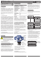
Product information and operating instructions
Radio actuator, 2-channel flush-mounted
Art.no.: FFA1210-0600
GB
1 17 00 94003 0
2-Kanal UP Schalt-Empfänger
Gehäusebedruckung
1
1
23.04.2003 Kleine
00
01
0-Serie
EnOcean Logo hinzu
23.04.
18.08.
Kleine
Junk
FS: \en tw_i nf\Proj ekte \e a sycl ick\ 2-K anal U P Sch alt -Ene mpf änge r\
Mod ulb esch reibung en\G eh ä useb edru cku ng\4 52 FU-E o.A .cdr
02
Abisolierung hinzu
25.08.
Junk
03
Textänderung
10.09.
Kleine
LRN/SET
CLR/MODE
9 mm
N N L
2
1
1 2
L max.2x500W
µ µ
FFA1210-0600
230V~
50Hz
extent
TM
Für diese Zeichnung beanspruchen wir alle Urheber-
rechte, auch für den Fall der Pa tentanmeldung oder Ge-
brauchsmustereintragung. Vervielfältigung oder Weiter-
gabe an Dritte nur nach unserer vorherigen Zustimmung.
Infratec
Dat entechnik GmbH
D a t u m
N o r m
Ä n d e r u n g
Name
Dateiname:
Blatt
Bl.
Urspr.:
Format DIN A4H
Datum
Zust.
G e p r.
Bearb.
N a m e
230V/50Hz~
LN
F
N N 1$ L 2$
LRN / SET
button with
LED 2
Learn mode
and function
programming
CLR / MODE
button with
LED 1
Delete all sen-
sors
and pa-
rameter setting
Learn mode:
LED = red
Function programming:
LED = green or orange
Output
1$
Channel 1
Output
2$
Channel 2
5. Operation
The radio actuator is operated with extent
TM
radio sensors
(radio signal). Before use, the radio sensors must be assi-
gned to the radio actuator (max. 32 radio sensors).
The radio actuator‘s Function 1 is preset after assigning
a radio sensor to the radio actuator. It can be changed by
function programming. Every radio sensor can control an
unlimited number of radio actuators.
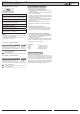
6. Programming
For programming, the radio actuators must be connected
to the mains power supply. The programming is retained
even in a power failure.
6.1 Learn mode (assigning or deleting radio sensors)
Notes:
– No radio sensor is assigned to the radio actuator
in its delivered state.
– A radio sensor can be assigned to channel 1 and 2!
– Several radio sensors can be assigned (max. 32
radio sensors) or deleted in learn mode.
–
A radio sensor is alternately assigned (LED on) or
deleted (LED off) each time the button is pressed!
– The radio actuator‘s Function 1 is preset after assigning
a radio sensor to the radio actuator. The function can be
changed for every radio sensor (see point 6.3).
– In order to delete a radio sensor, the channel (learn
mode)
to which it was assigned must be activated.
– If a radio sensor was assigned to both channels, it might
be necessary to delete it for both channel 1 and 2.
– If no action takes place, learn mode will be terminated
after 30 s.
6.2 Deleting all assigned radio sensors
CLR/MODE button long activation
All radio sensors deleted
Learn mode channel 1
(LED 1 blinks red)
LRN/SET button press 2x briefly
Idle state (LED off)
s. Point 6.1
General data
Transmit frequency 868,3 MHz
Power supply 230V~ / 50 Hz
Power line
protection
Circuit breaker rated
for 10 A, maximum
Ambient temperature - 20 to + 40°C
Storage temperature - 40 to + 85°C
Test specifications EN 60669-2-1
Identification CE ; KEMA/KEUR
Protection type IP20
Load types
Incandescent lamps
500 W
HV-halogen lamps
100 W
Inductive
100 VA
Electronic ballast 1 units
Range in buildings
Masonry 20m, through 3 walls max.
Reinforced concrete
10m, through 1 wall/ceiling max.
Plasterboard/wood 30m, through 5 walls max.
Activate radio sensor
once
(e.g. press button)
Sensor assigned
(LED 1 on)
Actuator = Function 1
Radio sensor deleted
(LED 1 off)
LRN/SET button
press briefly
Idle state
(LED off)
LRN/SET button
press briefly
Learn mode channel 1
(LED 1 blinks red)
LRN/SET button
press briefly
Learn mode channel 2
(LED 2 blinks red)
Activate radio sensor
once
(e.g. press button)
Sensor assigned
(LED 1 on)
Actuator = Function 1
Radio sensor deleted
(LED 1 off)