KRF EMC Filters Installation, Operation and Maintenance Manual KRF EMC Filters limit high frequency noise, as well as: • Reduce interference • Protect sensitive equipment • Eliminate drive cross-talk • Meet FCC Regulation 15, Subpart J
TCI, LLC W132 N10611 Grant Drive Germantown, Wisconsin 53022 Phone: 414-357-4480 Fax: 414-357-4484 Helpline: 800-TCI-8282 Web Site: http://www.transcoil.
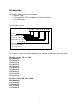
Introduction KRF EMC 3-Phase Filters are available: • 520V or 760V • Terminal Block (TB) or Copper Bus (CB) terminations • 8 to 2500 amps Part Number System: K R F 0 6 0 0 A C B K- Series 3-Phase EMI/RFI Filter Max Current (amps) Voltage Rating: A = 480 V V = 690 V Termination TB = Terminal Block CB = Copper Bus This manual is split into sections depending on voltage, termination, and amp rating: Section 1: 520V, TB, 8 – 150A Part Numbers: KRF0008ATB KRF0016ATB KRF0025ATB KRF0036ATB KRF0050ATB KRF0066AT
Section 3: 520V, CB, 150A & 600 – 2500A Part Numbers: KRF0150ACB KRF0600ACB KRF1000ACB KRF1600ACB KRF2500ACB Section 4: 760V, TB, 25 – 180A Part Numbers: KRF0025VTB KRF0036VTB KRF0050VTB KRF0080VTB KRF0120VTB KRF0150VTB KRF0180VTB Section 5: 760V, CB, 150 – 2500A Part Numbers: KRF0150VCB KRF0180VCB KRF0250VCB KRF0320VCB KRF0400VCB KRF0600VCB KRF1000VCB KRF1600VCB KRF2500VCB ii
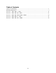
Table of Contents Cautions and Warnings ................................................................................................................... 1 Mounting Instructions ..................................................................................................................... 3 Section 1: 520V, TB, 8 – 150A................................................................................................... 11 Section 2: 520V, CB, 180 – 400A ................................................
iv
Cautions and Warnings Important Information Please read all safety and warning notes carefully before installing the EMC filter and putting it into operation (see ! ). The same applies to the warning signs on the filter. Please ensure that the signs are not removed nor their legibility impaired by external influences. Death, serious bodily injury and substantial material damage to equipment may occur if the appropriate safety measures are not carried out or the warnings in the text are not observed.
Important Notes The following applies to all products named in the publication: 1. Some parts of this publication contain statements about the sustainability of our products for certain areas of application. These statements are based on our knowledge of typical requirements that are often placed on our products in the areas of application concerned.
Mounting Instructions EMC cannot be ensured by the use of EMC filters alone. Every system should be considered as an integrated whole and careful planning and preparation are required to ensure success. Measures such as shielded motor cables, grounding and spatial separation are mandatory parts of an integrated concept. Plan your installation: • Identify interference sources (with interference emissions) and disturbed equipment (electrical equipment or components with limited interference immunity).
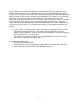
For operating currents greater than 250 A, we recommend the PE connection to be set up between the feed (filter: line) and output (filter: load) not via the PE terminal bolt in the filter housing. This is because of the restricted area of the cable lug of the PE connection to the filter housing. Ideally, the PE feed line should be connected with the PE output line to a PE busbar which also carries the PE terminal(s) of the EMC filter.
4. Keep cables from the interference source as short as possible! Examples: • Short connection from the converter to the EMC filter; ideally a flange mounted filter to avoid emissions. • Connection cables of minimum length between converter output and motor (also to reduce asymmetrical currents caused by the parasitic capacitances of the cable shield). 5.
• • • Connection cables between frequency converter and motor, if no corresponding output filter is used. Connection cables filter and converter on the line side, where not directly flange mounted It should be noted that the shielding effect of different cables can differ widely (foil shield, braided shield with various degree of coverage, combinations). 6.
7. Arrange EMC filters as far as possible directly at the entry or exit points of the housing Examples: • Line terminals are accessible via the corresponding opening of the equipment (ensure protection against electric shock). • Use of suitable EMC filters. • Use of corresponding housing matching elements to ensure the required shielding attenuation 8.
9. In order to reduce interference coupling, as far as possible run the cables close to metal parts which are connected to the reference potential (mounting plates, switch cabinet etc.) Live cables should also be run as close as possible to the reference potential (to reduce inductively coupled interferences). In order to improve electromagnetic compatibility, cable channels, cable trays and installation tubes which are made of metal rather than plastic parts should be preferred. 10.
11. Connect suitable EMC components close to switched inductors (e.g. contactors, relays, magnetic valves etc.). 12. For control signals in the vicinity of high interference levels, use transmission techniques such as: • Differential-mode transmission systems with twisted-pair lines in conjunction with data line chokes. • Transmission of digital signals according to the RS-422 standard or in extreme cases crossing the interference region with fiber-optic cables. 13.
• • As the parasitic currents flow via the ground connection of the installation, the sum of the input currents into the filter is no longer equal to zero. A specific magnitude of the parasitic current can lead to a saturation of the common-mode choke in the EMC filter and consequently exceed the permissible interference level. The interference voltage should therefore be measured on the installed equipment.
Section 1: 520V, TB, 8 – 150A EMC Filters Phase: 3 Current: 8 to 150 A Voltage: 520/300 V AC, 50/60 Hz Termination: Terminal Block Part Numbers: KRF0008ATB KRF0016ATB KRF0025ATB KRF0036ATB KRF0050ATB KRF0066ATB KRF0090ATB KRF0120ATB KRF0150ATB Construction • 3-line filter • Metal case • Book size Features • Excellent price/performance ratio • Ultra-compact design • Low weight • Easy to install • Optimized for long motor cables and operation under full load • ENEC10, UL, and cUL approval Applications • Frequ
Marking Marking on component: Manufacturer’s logo, ordering code, rated voltage, rated current, rated temperature, climatic category, date code Typical Circuit diagram Technical data and measuring conditions Rated voltage VR 520/300 V AC, 50/60 Hz Read current IR Referred to 40°C ambient temperature Leakage current Ileak 2236 V DC, 2 s (line/line) 2720 V DC, 2 s (lines/case) 1.5 · IR for 3 min per hour or 2.
Characteristics and part numbers VR AC V 520/300 IR A 8 16 25 36 50 66 90 120 150 Terminal cross section 2 mm 4 4 4 10 10 16 35 35 50 Ileak Rtyp mA µΩ 13 15 15 15 15 16 18 18 18 16 9 5 4 2 1.5 1.1 0.90 0.55 Approx weight kg Part Number 0.58 0.90 1.10 1.75 1.75 2.7 4.2 4.9 5.
Dimensional drawings (8 A) KRF0008ATB (16 A) KRF0016ATB 14
(25 A) KRF0025ATB (600 A) KRF0036ATB, KRF0050ATB 15
(66 A) KRF0066ATB (90 A) KRF0090ATB 16
(120 A) KRF0120ATB (150 A) KRF0150ATB 17
Insertion Loss (typical values at Z = 50 Ω) Unsymmetrical, adjacent branches terminated Common mode, all branches in parallel (asymmetrical) Differential mode (symmetrical) 18
Insertion Loss (typical values at Z = 50 Ω) Unsymmetrical, adjacent branches terminated Common mode, all branches in parallel (asymmetrical) Differential mode (symmetrical) 19
Insertion Loss (typical values at Z = 50 Ω) Unsymmetrical, adjacent branches terminated Common mode, all branches in parallel (asymmetrical) Differential mode (symmetrical) 20
Section 2: 520V, CB, 180 – 400A EMC Filters Phase: 3 Current: 180 to 400 A Voltage: 520/300 V AC, 50/60 Hz Termination: Copper Bus Part Numbers: KRF0180ACB KRF0250ACB KRF0320ACB KRF0400ACB Construction • 3-line filter • Metal case Features • Optimized leakage current • Easy to install • Very compact design • Optimized for operation under full load • Low weight • Design complies with EN 133200, UL 1283, CSA C22.2 No.
Typical circuit diagram Technical data and measuring conditions Rated voltage VR Read current IR Test voltage Vtest Overload capability (thermal) Leakage current Ileak Climatic category (IEC 60068-1) 520/300 V AC, 50/60 Hz Referred to 40°C ambient temperature (180 A filter at 60°C 2240 V DC, 2 s (line/line) 2690 V DC, 2 s (lines, case) 3270 V DC, 2 s (line/line) 2890 V DC, 2 s (lines/case) 1.5 · IR for 3 min per hour or 2.
Dimensional drawings (180 A, 250 A) KRF0180ACB, KRF0250ACB (320 A, 400 A) KRF0320ACB, KRF0400ACB 23
Insertion Loss (typical values at Z = 50 Ω) Unsymmetrical, adjacent branches terminated Common mode, all branches in parallel (asymmetrical) Differential mode (symmetrical) 24
Section 3: 520V, CB, 150A & 600 – 2500A EMC Filters Phase: 3 Current: 150 A; 600 to 2500 A Voltage: 520/300 V AC, 50/60 Hz Termination: Copper Bus Part Numbers: KRF0150ACB KRF0600ACB KRF1000ACB KRF1600ACB KRF2500ACB Construction • 3-line filter • Metal case Features • Optimized leakage current • Easy to install • Very compact design • Optimized for operation under full load • Low weight • UL, cUL approval Applications • Frequency converters for motor drives • Wind farms • Power supplies Terminals • Busbars
Typical circuit diagram Technical data and measuring conditions Rated voltage VR Read current IR Test voltage Vtest 530/310 V AC, 50/60 Hz Referred to 40°C ambient temperature 2280 V DC, 2 s (line/line) 2690 V DC, 2 s (lines, case) Overload capability (thermal) Leakage current Ileak Climatic category (IEC 60068-1) 1.5 · IR for 3 min per hour or 2.5 · IR for 30 s per hour At VR, 50 Hz 25/100/21 (-25°C/+100°C/21 days damp heat test) UL 1283; CSA C22.2 No.
Dimensional drawings (150 A) KRF0150ACB (600 A) KRF0600ACB 27
(1000 A) KRF1000ACB (1600 A) KRF1600ACB 28
(2500 A) KRF2500ACB Insertion Loss (typical values at Z = 50 Ω) Unsymmetrical, adjacent branches terminated Common mode, all branches in parallel (asymmetrical) Differential mode (symmetrical) 29
30
Section 4: 760V, TB, 25 – 180A EMC Filters Phase: 3 Current: 25 to 180 A Voltage: 760/440 V AC, 50/60 Hz Termination: Terminal Block Part Numbers: KRF0025VTB KRF0036VTB KRF0050VTB KRF0080VTB KRF0120VTB KRF0150VTB KRF0180VTB Construction • 3-line filter • Metal case Features • High insertion loss • Low leakage current • Easy to install • Degree of protection IP 20 (IEC 60529:2001) • Space saving design • Design complies with IEC/EN 60939, UL 1283, CSA 22.2 No.
Terminals • Finger-safe terminal blocks Marking Marking on component: Manufacturer’s logo, ordering code, rated voltage, rated current, rated temperature, climatic category, date code Typical Circuit diagram Technical data and measuring conditions Rated voltage VR 760/440 V AC Rated frequency fR 50/60 Hz Test voltage line to line for 2 s Test voltage line to case for 2 s Rated temperature Overload capability (thermal) for 3 min per hour or for 30 s per hour Leakage current Ileak Climatic category
Characteristics and part numbers IR 25 Terminal cross section 2 mm 10 36 A Ileak Rtyp mA µΩ Approx weight kg Part Number Approvals <7 8.0 4 KRF0025VTB 10 <7 3.8 4 KRF0036VTB 600/350V X X X X 50 10 < 12 2.0 4 KRF0050VTB - X X 80 25 < 12 1.0 9.5 KRF0080VTB - X X 120 50 < 12 0.75 10 KRF0120VTB - X X 150 50 < 12 0.4 10 KRF0150VTB - X X 180 95 < 12 0.
Dimensional drawings (25 A, 50 A) KRF0025VTB, KRF0050VTB (80 A) KRF0080VTB 34
(120 A, 150 A) KRF0120VTB, KRF0150VTB (180 A) KRF0180VTB 35
Insertion Loss (typical values at Z = 50 Ω) Unsymmetrical, adjacent branches terminated Common mode, all branches in parallel (asymmetrical) Differential mode (symmetrical) 36
37
Section 5: 760V, CB, 150 – 2500A EMC Filters Phase: 3 Current: 150 to 2500 A Voltage: 760/440 V AC, 50/60 Hz Termination: Copper Bus Part Numbers: KRF0150VCB KRF0180VCB KRF0250VCB KRF0320VCB KRF0400VCB KRF0600VCB KRF1000VCB KRF1600VCB KRF2500VCB Construction • 3-line filter • Metal case Features • Optimized leakage current • Easy to install • Very compact design • Optimized for operation under full load • Low weight • UL, cUL approval Applications • Frequency converters for motor drives • Wind farms • Powe
Technical data and measuring conditions Rated voltage VR Read current IR Overload capability (thermal) Leakage current Ileak Climatic category (IEC 60068-1) Type: 760/440 V AC, 50/60 Hz Referred to 40°C ambient temperature Type: 3270 V DC, 2 s (line/line) 2890 V DC, 2 s (lines/case) 1.5 · IR for 3 min per hour or 2.5 · IR for 30 s per hour At VR, 50 Hz 25/100/21 (-25°C/+100°C/21 days damp heat test) UL 1283; CSA C22.2 No.
(150 A, 180 A) KRF0150VCB, KRF0180VCB (250 A) KRF0250VCB (320 A, 400 A) KRF0320VCB, KRF0400VCB 40
(600 A) KRF0600VCB (1000 A) KRF1000VCB 41
(1600 A) KRF1600VCB (2500 A) KRF2500VCB 42
Insertion Loss (typical values at Z = 50 Ω) 43
Unsymmetrical, adjacent branches terminated Common mode, all branches in parallel (asymmetrical) Differential mode (symmetrical) 44
45
TCI, LLC W132 N10611 Grant Drive Germantown, Wisconsin 53022 Phone: 414-357-4480 Fax: 414-357-4484 Helpline: 800-TCI-8282 Web Site: http://www.transcoil.com © 2011 Part Number: 27781 Version 1.