
Manual


70
Installation Guidelines
Checklist
The following are the key points to be followed for a successful installation. These points are explained in
detail in the following sections.
o Make sure the installation location will not be exposed to direct sunlight, excessive
vibration, corrosive or combustible airborne contaminants, excessive dirt or liquids.
o Select a mounting area that will allow adequate cooling air.
o Make sure that all wiring conforms to the requirements of the National Electric Code
(NEC) and/or other applicable electrical codes.
o Ground the HMI display by using the grounding terminal. Not only does this act as a
safety, but it also filters out electrical noise.
o Check all connections and components thoroughly before applying power to the
equipment.
o Check the panel and the inside of the enclosure for any foreign objects, dirt
and/or loose hardware.
Location
Environment
The location of the Interface Module should be a suitable environment to assure proper performance and a
normal operating life. Refer to the environmental specifications furnished in this manual, and noted on the
drawings with the Interface Module.
Warning
Unless specifically labeled as approved for such use, this equipment is not suitable for use in an
explosive atmosphere or in a "Hazardous (Classified) Location" as defined in article 500 of the National
Electrical Code (NEC).
• Display front rated Type 1 & 4X
• Avoid direct sunlight
• Avoid corrosive liquids or gasses
• Avoid explosive or combustible gases or dust
• Avoid excessive airborne dirt and dust (Pollution Degree 2, according to EN50178 and UL508C)
• Avoid excessive vibration (0.152 mm (0.006 in.) displacement, 1G peak)
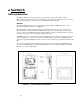
Mounting
Mounting requires at least a depth of 4” (102 mm). The Interface Module will mount in a panel with a
thickness of 0.02 to 0.35 inch (0.5-9.0 mm) with an opening 6.79” by 5.21” (173 by 133 mm). Fit the
Interface Module assembly into the opening carefully pressing on all four corners. Use the mounting
hardware (4 sets) to secure the assembly on the corners.
Warning: to avoid damaging the case, do not exceed a tightening torque of 3.47 to 4.34 lbs-in (0.39-0.49
Nm). Care should be taken not to mount the Interface Module too close to a heat source (such as power
resistors) which could be located behind the Interface Module.
!