
Manual


7
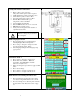
1) Verify unit external connections
• Phase A, B, C power connection,
with positive A-B-C phase rotation expected
• CT H1 Terminal is pointing toward the source
• CT feedback on phases A & C to TB-1
• Leave CT shorting bars in place on TB-1
• With the HGA circuit breaker open,
energize the source to the HGA
• Close the HGA circuit breaker
• Fans and HMI should come on in < 5 seconds
• HMI will start on Home screen
• Load(s) have an integral 5% line reactance or
equivalent dc bus choke
Warning
Hazardous voltages are present when
unit is energized
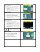
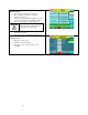
NOTE: Language Selection
• The active filter supports several languages
including English, French and Spanish
• Press “Setup” to navigate to Setup screen and
press the “Language Setup” button.
•
Select language setting from the language setup
pop-up screen.
2) Converter check - 1
• Press “Setup” to navigate to Setup screen
• Ensure that “Auto Start En,” “Harmonic
Correct En,” and “PWR Fact Correct En”
buttons are off (blue color)
• If they are ON (green) press them to toggle to OFF
(blue)
• Press “Save Settings”
• Press “Status” to navigate to Status screen
• Press “Home” to navigate to Home screen
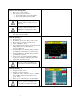
NOTE: Built In Sensor Wiring Error Detection
• The active filter has an automatic sensor wiring
error detection algorithm built in to the controls.
• If a sensor wiring error is detected please reference
the Sensor Error Auto Detection section on page
93.
!