
Manual

48
Reference Drawings
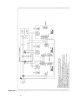
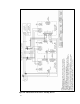
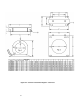
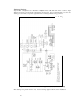
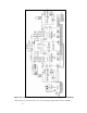
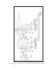
Typical HGA configurations are illustrated in Figures 5.1a, 5.1b, and 5.1c. There could be slight
differences between your unit and the configurations shown below. It is recommended that you refer to the
drawings provided with your specific equipment when conducting troubleshooting operations.
Figure 5.1a – General Schematic Bus Applied 39, 45, 78, 90 and 100 amp
*This drawing is for general reference only. Use the drawings supplied with the unit for installation.