Active Harmonic Filter Installation, Operation, and Maintenance Manual TCI, LLC W132 N10611 Grant Drive Germantown, Wisconsin 53022 Phone: 414-357-4480 Fax: 414-357-4484 Helpline: 800-TCI-8282 Web Site: http://www.transcoil.
No part of this publication may be reproduced, stored in a retrieval system, or transmitted in any form or by any means, mechanical, electronic, photocopying, recording, or otherwise, without the prior written permission of TCI, LLC. The information in this manual is subject to change without notice. Every precaution has been taken in the preparation of this manual. TCI, LLC assumes no responsibility for errors or omissions.
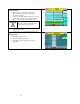
Table of Contents ■ Section 1 HGA Quick Start Unit Software Setup.......................................................... 6 ■ Section 2 Safety Instructions ...................................................................................... 11 Overview ............................................................................................................................................... 11 Warnings and Cautions .....................................................................................
Installation Guidelines ................................................................................ 29 Mounting .............................................................................................................................................. 29 Wiring ................................................................................................................................................... 29 Current Transformer Installation ..........................................................
■ Section 8 Maintenance ................................................................................................. 96 Clock Battery Replacement ................................................................................................................ 97 Software Field Upgrades ..................................................................................................................... 97 Troubleshooting ...................................................................................
■ Section 1 HGA Quick Start Unit Software Setup Warning ! Warning ! Warning ! Warning Be sure to read, understand, and follow all safety instructions. Only qualified electricians should carry out all electrical installation and maintenance work on the HarmonicGuard Active (HGA) filter. All wiring must be in accordance with the National Electrical Code (NEC) and/or any other codes that apply to the installation site. Disconnect all power before working on the equipment.
1) Verify unit external connections • • • • • • • • • Phase A, B, C power connection, with positive A-B-C phase rotation expected CT H1 Terminal is pointing toward the source CT feedback on phases A & C to TB-1 Leave CT shorting bars in place on TB-1 With the HGA circuit breaker open, energize the source to the HGA Close the HGA circuit breaker Fans and HMI should come on in < 5 seconds HMI will start on Home screen Load(s) have an integral 5% line reactance or equivalent dc bus choke Warning ! Hazardou
3) Home screen check • • • • Compare “Freq” to expected line frequency Compare “Supply Voltage” to expected line voltage “Current” expected to be zero because unit is not running and CT inputs are shorted If status indicates a Fault, press “Stop” button to reset condition 4) Status screen check • • • • Press “Status” to navigate to Status screen Compare “Volts” to expected line voltage Compare “Freq” to expected line frequency “Current” expected to be zero if unit is not running and CT inputs are shorted
7) Remove CT shorting bars • Press “Stop” to turn off unit • Disconnect power from cabinet o Turn off the built in door breaker AND o Turn off the upstream feeder breaker Warning Lethal voltages may be present. Wait 5 minutes for DC bus voltage to drop to safe levels. Warning • Check for voltage in cabinet with a DMM before working inside cabinet.
) Final setup • Press “Setup” to navigate to Setup screen • Press “Harmonic Correct En” to enable harmonic correction • If unit is sized with sufficient capacity to provide power factor correction, press “PF Correct En” • Press “Auto Start En” to enable Autostart Warning When Auto Start is enabled unit may operate without operator input.
■ Section 2 Safety Instructions Overview This section provides the safety instructions which must be followed when installing, operating, and servicing the HarmonicGuard Active (HGA) filter. If neglected, physical injury or death may follow, or damage may occur to the HGA filter or equipment connected to the HGA filter. The material in this chapter must be read and understood before attempting any work on or with the product.
Cautions Readers are informed of situations that can lead to a malfunction and possible equipment damage with caution statements: Caution ! General Caution: Identifies situations that can lead to a malfunction and possible equipment damage. The text describes ways to avoid the situation. General Safety Instructions These safety instructions are intended for all work on the HGA filter. Additional safety instructions are provided at appropriate points on other sections of this manual.
General Terminology Throughout this manual, many different terms are used. A list of some typical terms can be found below. These are provided in order to assist with the overall understanding of the manual. Please feel free to contact TCI directly if there are any questions regarding any portion of this manual. HarmonicGuard Active Filter - TCI’s brand name for a real time filter that mitigates harmonics while also maintaining near unity power factor.
■ Section 3 Introduction Thank you for selecting TCI’s HarmonicGuard Active filter. TCI has produced this filter for use in variable speed drive and non-linear load applications that require input power line harmonic current reduction and power factor correction. This manual describes how to install, operate, and maintain the HarmonicGuard Active filter.
Receiving Inspection and Storage Receiving Inspection The HarmonicGuard Active filter has been thoroughly inspected and functionally tested at the factory and carefully packaged for shipment. When you receive the unit, you should immediately inspect the shipping container and report any damage to the carrier that delivered the unit. Verify that the part number of the unit you received is the same as the part number listed on your purchase order.
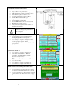
Product Description HarmonicGuard Active filter The HarmonicGuard Active filter is an active harmonic filter designed and developed by TCI to relieve the power distribution system of the issues associated with harmonic currents that flow within the power distribution network caused by non-linear loads. The typical configuration can be found in Figure 3.1.
Filter Configuration Figure 3.1 – Typical Configuration of the HarmonicGuard Active filter *This drawing is for general reference only. Use the drawings supplied with the unit for installation.
Nameplate Data Figure 3.2 shows a typical HarmonicGuard Active filter nameplate. The following information is marked on the nameplate: Part number: encoding is explained on the following page Corrective Current: The maximum amount of RMS Corrective Current the unit can deliver. System Voltage: the rated 3-phase line voltage (RMS volts) Hz: the rated frequency (60 Hz) Phase: 3, 3 Wire – The HGA is designed for use with only 3 wire systems with balanced 3phase voltage source.
Part Number Encoding Figure 3.3 identifies the significance of each character in the HarmonicGuard Active filter part number. An example of a completed part number would be ALC100A01H2000. This designates an enclosed HarmonicGuard Active filter that is rated for 100 amps, 480 volts, and has an HMI Interface Module Package.
Figure 3.4 identifies the significance of each character in the HarmonicGuard Active filter part number. An example of a completed part number would be H5100A03H4000. This designates an enclosed HarmonicGuard Active filter that is rated for 100 amps, 480 volts, and has an HMI Interface Module Package. HGA Part Numbering System – 480V 3R Temperature: 40° C Current: 50, 100, 200, 300 Voltage: 480 Enclosure: UL Type 3R Figure 3.
Figure 3.5 identifies the significance of each character in the HarmonicGuard Active filter part number. An example of a completed part number would be H5300A00H1000. This designates an enclosed HarmonicGuard Active filter that is rated for 300 amps, 480 volts, and has an HMI Interface Module Package. HGA Part Numbering System – 480V 300A Temperature: 40° C Current: 300 Voltage: 480 Enclosure: UL Type 1 or UL Type 3R Figure 3.
Figure 3.6 identifies the significance of each character in the HarmonicGuard Active filter part number. An example of a completed part number would be H5039C033H0100. This designates an enclosed HarmonicGuard Active filter that is rated for 39 amps, 600 volts, and has an HMI Interface Module Package. HGA Part Numbering System – 600V Temperature: 40° C Current: 39, 78 Voltage: 600 Enclosure: Open Chassis, UL Type 1 or UL Type 3R Figure 3.
Figure 3.7 identifies the significance of each character in the HarmonicGuard Active filter part number. An example of a completed part number would be ALC45A01H10. This designates an enclosed HarmonicGuard Active filter that is rated for 45 amps, 480 volts, and has an HMI Interface Module Package. HGA Part Numbering System – 480V Open & Type 1 (50° C) Temperature: 50° C Current: 45, 90 Voltage: 480 Enclosure: Open Chassis or UL Type 1 Figure 3.
Communications Part Numbering Table 3.1 below shows the HGA part numbering with the communications part numbers. The base communications unit is CM100A00 which has both the HMI and Modbus. Table 3.
Table 3.4 – UL Type 3R Enclosed Amps HeatLoss (watts) 39 50 78 100 200 300 Consult Factory 3176 Consult Factory 3500 7000 Consult Factory Dimensions Inch (cm) HxWxD Weight lbs. (kg) 371 (168.3) 80.00 (203.2) 32.00 (81.3) 25.00 (63.5) 371 (168.3) 1040 (472) 80.00 (203.2) 80.00 (203.2) 32.00 (81.3) 57.00 (144.78) 25.00 (63.5) 25.00 (63.5) Table 3.5 – Transformer for 600V units – Open and Type 3R Amps Encl. 39 78 39 78 Open Open 3R 3R 25 Heat Loss (watts) 345 740 345 740 Weight lbs.
Table 3.6 – HarmonicGuard Active filter Technical Specifications Voltage ratings 480V, 3 phase, 60 Hz, three wire systems Phase Sequence Positive phase rotation: A-B-C (or L1-L2-L3) Load types Current ratings Maximum elevation Maximum Ambient operating temperature 3-phase diode bridge rectifier loads such as PWM AC drives *3-phase controlled rectifier (SCR or thyristor) loads such as DC drives See Ratings in Standard Product Rating and Dimensions tables.
■ Section 4 Pre-installation Planning Verify the Application HGA Ratings Make sure that the HarmonicGuard Active filter is correct for the application and sized for load. The voltage ratings of the HGA must match the input voltage rating of the connected AC bus. Select a Suitable Location Environment Locating the HarmonicGuard Active filter in a suitable environment will help assure proper performance and a normal operating life. Refer to the environmental specifications listed in Table 3.
Figure 4.
Figure 4.
Installation Guidelines Mounting The HGA must be mounted vertically on a smooth, solid surface, free from heat, dampness, and condensation. Wiring Cable Entry Locations The enclosed HarmonicGuard Active filters are not provided with enclosure wiring knockouts, however, a removable wire entry plate is provided. A selection can be made at the time of installation. Typical or recommended cable entry locations are shown in the drawings shipped with the unit.
Table 4.1b – Power Terminal Wire Size (without breaker) Capacity Range and Tightening Torque 39 to 100 Amp Ground Lug Wire Size Torque In-lbs (Nm) 14 AWG – 2/0 120 (13.6) 150 to 200 Amp 14 AWG – 2/0 120 (13.6) Breaker IC 25 to 100 kA 25 to 100 kA 150 to 200 Amp 14 AWG – 2/0 120 (13.6) None Chassis Size Control Terminals Caution ! Power Terminals Wire Size Torque In-lbs (Nm) 14 – 2/0 AWG 180 (20.3) 6 AWG – 350 MCM 274 (31) 6 AWG – 350 MCM 274 (31) Wire Size 28 to 14 AWG Torque 4.
Current Transformer Installation For accurate sensing of the load it is important that the load sensing current transformers are properly installed. Warning ! Only qualified electricians should carry out all electrical installation and maintenance work on the HGA. Failure to follow standard safety procedures may result in death or serious injury. Disconnect all sources of power to the drive and HGA before working on the equipment. Do not attempt any work on a powered HGA.
Current Transformer Diagrams The following pages contain detailed diagrams on the placement of CTs in relation to the HGA. Figure 4.4a Line Side or Load Side CT Placement for stand-alone HGA filters rated at 45 to 100 amps, 480V. Figure 4.4b Line Side or Load Side CT Placement for stand-alone HGA filters rated at 39 to 78 amps, 600V. Figure 4.4c Line Side or Load Side CT Placement for stand-alone HGA filters rated at 200 amps, Open or Type 1, 480V. Figure 4.
Figure 4.
Figure 4.
Figure 4.
Figure 4.
Figure 4.
Figure 4.
Figure 4.
Figure 4.
Figure 4.
Figure 4.5 – Current Transformer Diagram – Round Figure 4.
Figure 4.
Grounding The HarmonicGuard Active filter panel equipment-grounding lug must be connected to the ground of the premises wiring system. The equipment grounding connection must conform to the requirements of the National Electric Code (NEC) and/or any other codes that apply to the installation site. The ground connection must be made using a wire conductor. Metallic conduit is not a suitable grounding conductor. The integrity of all ground connections should be periodically checked.
■ Section 5 Maintenance and Service HGA Reliability and Service Life The HGA has been designed and thoroughly tested at the factory to ensure that it will perform reliably from the time it is put into service. The following periodic maintenance is recommended to ensure that the HarmonicGuard Active filter will always perform reliably and provide the expected service life. Periodic Maintenance The following checks should be conducted monthly or more frequently when installed in harsh or dusty environments.
Reference Drawings Typical HGA configurations are illustrated in Figures 5.1a, 5.1b, and 5.1c. There could be slight differences between your unit and the configurations shown below. It is recommended that you refer to the drawings provided with your specific equipment when conducting troubleshooting operations. Figure 5.1a – General Schematic Bus Applied 39, 45, 78, 90 and 100 amp *This drawing is for general reference only. Use the drawings supplied with the unit for installation.
Figure 5.1b – General Schematic Bus Applied 200 Amp, Open and Type 1, Master/Master *This drawing is for general reference only. Use the drawings supplied with the unit for installation.
Figure 5.1c – General Schematic Bus Applied 200 Amp, Type 3R, Parallel *This drawing is for general reference only. Use the drawings supplied with the unit for installation.
Overload / Over Current Protected The filter has factory set built-in electronic overload and over current protection. If the converter current exceeds the preset instantaneous peak, the converter will shut down to prevent permanent damage to the converter, and at which time it will indicate a fault. Faults that do not automatically reset can be cleared by pressing the stop button on the HMI display.
have failed or something more serious with the operation of the converter. For this reason this fault will latch and will remain latched until power is cycled. The indicator light located on relay CR-2 will not be lit with this type of over temp fault. Troubleshooting Current Transformer Orientation Troubleshooting Failure to maintain the correct polarity and phasing of the current transformers (CTs) will cause an over current fault on power up.
Warning Only qualified electricians should carry out all electrical installation and maintenance work on the HGA. Disconnect all sources of power to the drive and HGA before working on the equipment. Do not attempt any work on a powered HGA. This HGA unit contains high voltages and capacitors. Wait at least five minutes after disconnecting power from the filter before you attempt to service the conditioner. Check for zero voltage between all terminals on the capacitors.
Converter Inspection • Verify that power has been removed from converter, and 5 minutes has passed before inspection. • Remove plastic cover from over converter section. • Visually check the circuit boards for debris; contamination; overheated traces; burnt circuit board; overheated, cracked, or broken components; corrosion; and poor solder joints. • Check all wires and terminals connected to the circuit boards.
Figure 5.3 – TB-1 Terminal Block Warning Only qualified personnel should operate the HarmonicGuard Active filter with the door open. Failure to follow standard safety procedures may result in death or serious injury. Do not attempt any work on a powered filter converter. The HGA contains high voltages and capacitors. Wait at least five minutes after disconnecting power from the converter before you attempt servicing. Check for zero voltage between all terminals to the converter.
Figure 5.
Replacement Parts If replacement parts are needed, please contact your TCI representative. To ensure that the HarmonicGuard Active filter continues to perform to its original specifications, replacement parts should conform to TCI specifications. Use of non-TCI approved components will void all warranties. Factory Contacts and Technical Support For technical support, contact your local TCI distributor or sales representative. You can contact TCI directly at 1-800-824-8282.
Figure 5.
Figure 5.
Figure 5.
Figure 5.
Figure 5.
Figure 5.
Figure 5.
Figure 5.
Figure 5.
Figure 5.
■ Section 6 HMI Introduction The Interface Module provides the user with a convenient way to monitor the operation of TCI’s HarmonicGuard Active filter and allows for the ability to adjust run-time set-points under password control. This section describes how to install, operate, and maintain the Interface Module. Overview The Interface Module has three major components; the Interface PCB, the HMI Display and an option network Communications Gateway (see Figure 6.1).
Additional Information Caution ! This section provides general information describing the Interface Module. Be sure to carefully review the more specific information provided by the drawings shipped with the module. Information from by the drawings takes precedence over the information provided in this section. The information and ratings given in this manual are approximate and should not be used for any purpose requiring exact data. Contact the factory in situations where certified data is required.
Installation Guidelines Checklist The following are the key points to be followed for a successful installation. These points are explained in detail in the following sections. o Make sure the installation location will not be exposed to direct sunlight, excessive vibration, corrosive or combustible airborne contaminants, excessive dirt or liquids. o Select a mounting area that will allow adequate cooling air.
Caution ! Warning The display panel is waterproof. But care should be taken to prevent grease, corrosive liquids and sharp objects from contacting the front panel. Many electronic components located within the Interface Module and HMI are sensitive to static electricity. Voltages imperceptible to human touch can reduce the life, and affect performance, or completely destroy sensitive electronic devices. Use proper electrostatic discharge (ESD) procedures when servicing the Interface Module and HMI.
Interface PCB Connections Most customer connections to the Interface module will be made on the Interface PCB. Refer to connection diagrams in Figure 6.3. The details of the power and communications terminals are shown in Table 6.1, form C relays are available on the Interface PCB. These connections are shown in Table 6.2. Four outputs are available on the Interface PCB.
Table 6.2 – Form C Relay Contacts Terminal Pin Description Label Tightening Torque Wire Range 1 Normally Closed Run 4.4 lbs-in (0.5 Nm) 28-14 Awg 2 Common 3 Normally Open 1 Normally Closed J6 Power On 4.4 lbs-in (0.5 Nm) 28-14 Awg 2 Common 3 Normally Open 1 Normally Closed J7 Fault 4.4 lbs-in (0.5 Nm) 28-14 Awg 2 Common 3 Normally Open 1 Normally Closed Current J12 4.4 lbs-in (0.5 Nm) 28-14 Awg 2 Common Limit 3 Normally Open Note: Form-C relay contacts are gold plated with a load rating of 0.
ModbusRTU Connection Figure 6.4 – HMI ModbusRTU Connection Table 6.4 – Modbus Connector Pin Definitions COM2/3 Signal Name Signal Type DB9 Pin 1 no connect 2 no connect 3 no connect 4 D+ RS-485 B (non-inverting) 5 GND RS-485 SC/G 6 no connect 7 no connect 8 no connect 9 DRS-485 A (inverting) Table 6.
■ Section 7 Operation HMI Screen Elements This section focuses on the operation of the HMI Display. The HMI Display contains several screens that allow the user to monitor the status of the line/load and the HarmonicGuard Active filter. Additionally the HMI display can be used for local run/stop control and basic setup of the HarmonicGuard Active filter. HMI Graphic Element Buttons Indicators Table 7.
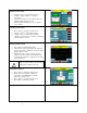
Title Bar HMI Display Power LED Indicator Button Numerical Display Navigation Bar Figure 7.1 – HMI Display Initialization When first powered, the green LED (Power) on the HMI Display will light (see Figure 7.1). After a five second boot up sequence the Home Screen will be displayed. If the home screen is not displayed and power is available to the HMI Display see the troubleshooting section at the end of this user manual for diagnosing common problems.
Screen Element Table 7.2 – Home Screen Elements Description Filter Status Display Indicates if a converter fault is active and preventing the HarmonicGuard Active filter from running. If a fault occurs the indicator will flash red and display “Fault”. Specific Fault codes can be viewed on the “Fault” Screen. % Filter Current Used Display This gauge displays the current filter capacity as a percentage of total available capacity. In normal operation the display will read “Nominal”.
Status Screen The Status screen shows more specific information on the performance of the system such as current and voltage waveforms, Power Factor and information specific to the Line/Load screen and Converter screen. Figure 7.3 explains the main “Status” Screen. Figure 7.3 – Status Screen Table 7.3 – Status Screen Elements Screen Element Description Line/Load Button Use this button to get to the “Line/Load Status” Sub Screen (see Figure 7.6).
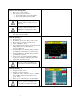
Converter Status Sub Screen The converter status sub screen shows the present status of the HarmonicGuard Active filter power converter module. Figure 7.4 – Converter Status Sub Screen Table 7.4 – Converter Status Sub Screen Elements Screen Element Description Run/Stop Button Runs and stops the HarmonicGuard Active filter. Current Display Displays the present HarmonicGuard Active filter output corrective current in Amps RMS.
Run Enable Summary Sub Screen The Run Enable Summary sub screen shows state of all the enables that affect the running of the HarmonicGuard Active filter. Figure 7.5 – Run Enable Summary Sub Screen Table 7.5 – Run Enable Summary Sub Screen Elements Screen Element Description Run/Stop Button Local HMI Enabled Auto Start Remote Relay Remote Network Back 80 Runs and stops the HarmonicGuard Active filter. Shows if the start or stop button is enabled.
Line/Load Status Sub Screen The Line/Load Status Sub Screen shows more specific information regarding the source and load voltage, current, power, power factor and THD measurements. Figure 7.6 – Line/Load Status Sub Screen Table 7.6 – Line/Load Status Sub Screen Elements Screen Element Volts Display Displays the current utility phase to phase line voltage in Volts RMS. Displays the current line/load phase current in Amps RMS.
Waveform Plot Sub Screens The HMI display supports capture and display of real time system voltage and current data. Three phase waveform data can be viewed for Line Voltage, Line/Load Current, and Converter Corrective Current. The waveform screens contain a zoom feature which supports three magnitude scales: 1 X, 2 X and 4X (see Figure 7.7). The Refresh button on the waveform screens will update the plot with new data from the HarmonicGuard Active filter converter. Figure 7.
Figure 7.8 – VLine & ILine Waveform Plot of a Properly Connected HarmonicGuard Active filter (unit in stopped state) Note: The example VLine & ILine Waveform Plot screens apply to rectifier loads only. For low power factor loads the VLine & ILine waveform screen will appear different. Table 7.8 shows what the VLine & ILine Waveform Plot Sub Screen would look like with various connection errors present in the system. Table 7.
Phase C system CT current feedback missing: Check Phase C CT for open circuit or loose connection. Phase C current is zero while Phase A current is present. Phase A and Phase C CT current feedback swapped: Phase A current (red) in phase with Phase C voltage (blue) instead of Phase A voltage (green). Phase A current (red) is opposite polarity of Phase A voltage (green) and Phase C current (yellow) is opposite polarity of Phase C voltage (blue).
Historical Trend Plot Menu Sub Screen From the historical trend plot menu sub screen you can view trend graphs of various HarmonicGuard Active filter system signals (see Figure 7.10). Figure 7.9 – Historical Trend Plot Menu Sub Screen Table 7.9 – Historical Trend Plot Menu Sub Screen Elements Screen Element Description Converter Temp Button Opens the HarmonicGuard Active filter heatsink temperature historical trend graph screen.
Historical Trend Plot Sub Screens The historical trend plot screens graph time-stamped feedback data over an extended period of time. Once the trend plot display data buffer is full the oldest data is overwritten. Historical data can be viewed using the integrated scroll bars of the trend plot. All trend plot data is maintained between power on/off cycles of the HarmonicGuard Active filter. See Figure 7.
Fault Screen This button takes the user to the “Active Fault” screen (see Figure 7.11) which lists all of the active faults. The faults will stay in this list until the “Reset”, or “Stop” button is pressed or the fault self clears. From here the user can also go to the “Fault History” screen. Figure 7.11 – Fault Screen Table 7.11 – Fault Screen Elements Screen Element Description Stop Button Reset Button Fault Trip Entry Display History Button 87 Turns off the HarmonicGuard Active filter.
Fault Code 10 20 30 1000 1250 3000 3010 3020 4000 4250 7000 7010 Table 7.
Figure 7.12 – Fault History Sub Screen Table 7.13 – Fault History Log Entry Format Column (from left to right) Onset/Clear Marker Format Timestamp O = Fault Onset X = Fault Cleared HH:MM MM/DD/YYYY Fault Code Fault Description Four digit code Text Description Marks the start and end of a fault in the fault history. Time and date the fault entry was logged. Fault code (see Table 7.
Figure 7.14 – Setup Screen Table 7.14 – Setup Screen Elements Screen Element Description Auto Start Enable Button Harmonic Correction Enable Button Network Start Enable Button Relay Start Enable Button Factory Setup Button Set Date and Time Button Power Factor Correction Enable Button Screen Brightness Button 90 This option will set the converter to start automatically after a programmed delay after power is applied or after a fault occurs. This option is on by default.
Close screen Contrast (disabled) Brightness Gamma Network Setup Button This option lets the user view the status of and configure the integrated ModbusRTU network connection in the HMI display This button is password protected and used during technician setup and commissioning only.
Network Setup Sub Screen The network setup sub screen (see Figure 7.15) allows the user to view and configure the network interface options available internally to the HMI Display. For details on the integrated Modbus RTU interface connections see the HMI Display Connections section. If an optional advanced network Communications Gateway is configured please reference the appropriate Gateway section in the Appendix.
remotely will be lost. TCI will not be responsible for the loss of communication due to this change. About Screen The About Screen (see Figure 7.16) displays model number, serial number, and software/firmware version information regarding the filter. Figure 7.16 – About Screen Screen Element Stop Button Serial # Display Turns off the HarmonicGuard Active filter. Displays the pre-programmed factory serial number of the HarmonicGuard Active filter.
Sensor Wiring Error Auto Detection Sub Screen Some HarmonicGuard Active filter models are equipped with voltage and current feedback sensor wiring error detection algorithms. The detection algorithms run briefly on unit power up and check the unit sensors for signatures of common wiring errors, such as incorrect ACB phase rotation (instead of the required ABC rotation) and inverted system CT polarity.
Error Code Table 7.18 – Sensor Wiring Error Code Table Error Suggested Corrective Action 0 No Error No corrective action required. 1 Self Test In Progress No correction action required. Typically the self test will complete and auto clear in less than 10 seconds after power up.
Network Interface The network interface on the Interface Module allows basic Run/Stop commands and internal status data and can be communicated to and from the HarmonicGuard Active filter. The HMI display implements an integrated ModbusRTU slave device for the network interface (see the HMI Display Connection section) or an optional network communications gateway can be used such as Ethernet/IP to implement other protocols (see Appendix).
■ Section 8 Maintenance Clock Battery Replacement The HMI Display Real Time Clock is maintained by a non-rechargeable battery internal to the HMI Display. Change the battery every ten years or as needed. The system will continue to function as an active filter with a dead battery but HMI information (fault logs and trend plots) will not be maintained between power cycles. To replace the battery, open the battery cover on the back of the HMI Display (see Figure 8.1) and remove the old battery.
Troubleshooting HarmonicGuard Active Filter Fault If the display indicates a fault has occurred proceed to the fault screen by choosing the “Fault” menu screen button. To see if this is a recurring fault hit the “History” button from inside the “Fault” screen. To clear a fault press the “Reset” button from inside the “Fault” Screen or the “Stop” button from any screen. Warning Only qualified electricians should carry out all electrical installation & maintenance work on the HGA.
Warning Many electronic components located within the filter are sensitive to static electricity. Voltages imperceptible to human touch can reduce the life, affect performance and/or destroy sensitive electronic devices. Use proper electrostatic discharge (ESD) procedures when servicing the filter and its circuit boards. Troubleshooting Notes • To reboot the system, remove power to the filter and Interface Module, wait a few minutes then reapply.
■ Section 9 Appendix – Installation Diagram Figure 9.
Appendix – Part Numbering Part numbering: Here is an example the interface module part number: CM100A00 CM = Communications 100 = amp rating of 100 amps A = voltage rating of 480V 00 = Modbus RTU over RS485 A suffix of 00 = Modbus RTU over RS485 A suffix of 01 = Ethernet/IP Here would be the part number possibilities available as of this revision: CM45A00, CM50A00, CM90A00, CM100A00, CM200A00, CM45A01, CM50A01, CM90A01, CM100A01, CM200A01 101
Appendix – Ethernet/IP Gateway Option Introduction The EtherNet/IP network Communications Gateway translates command/status data to/from the HMI Display’s integrated network interface from the ModbusRTU protocol to EtherNet/IP. The EtherNet/IP Communications Gateway is implemented using a third party, industry leading EtherNet/IP solution from HMS Anybus Communicator Product Line (Anybus Communicator AB7007). Table 9.
Table 9.2 – EtherNet/IP Connector Pinout Pin Number Description 1 TD+ 2 TD- 3 RD+ 6 RD- 4, 5, 7, 8 Termination Configuration To configure the IP address of the EtherNet/IP communications gateway connect the gateway to the Ethernet network then open a web browser window and type in the default IP address of the gateway (see Table 9.2) and press enter. The Communications Gateway configuration page should load (see Figure 9.3). Figure 9.3 – EtherNet/IP Gateway Configuration Page Table 9.
To update the IP address, type in a new IP address on the configuration page then click on the STORE CONFIGURATION button. After the new IP address is stored, cycle power to the Communication Gateway to load the new IP address. The EtherNet/IP Communications Gateway supports implicit Ethernet/IP I/O and explicit Ethernet/IP CIP Message commands.
TCI, LLC W132 N10611 Grant Drive Germantown, Wisconsin 53022 Phone: 414-357-4480 Fax: 414-357-4484 Helpline: 800-TCI-8282 Web Site: http://www.transcoil.