
Manual Revision 2.1


8
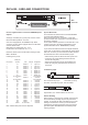
dsp 6000 - Card and COnneCTIOns
Use the supplied cable to connect the AES/EBU Inputs/
Outputs.
Cable type is twisted pair (12 pairs) with common screen.
Recommended impedance: 110 Ohm.
OneendisequippedwithanAES/EBU25pinDSub
connector,theotherendisequippedwithfourmaleXLR’s
andfourfemaleXLR’s.
MaleXLR’saremarkedwith:Out-1to4.
FemaleXLR’saremarkedwith:IN-1to4.
Extension cables must be constructed according to AES/
EBU-3standards.
Following is the pin-out:
Cable pair
Pinnumber number XLR XLR-pin Assignment
1 1a Female 1 2 Input 1/2 +
2 2a Female 2 2 Input 3/4 +
3 3a Female 3 2 Input 5/6 +
4 4a Female 4 2 Input 7/8 +
5 5a Male 1 2 Output 1/2 +
6 6a Male 2 2 Output 3/4 +
7 7a Male 3 2 Output 5/6 +
8 8a Male 4 2 Output 7/8 +
9 No connection No connection
10 9a Female 1 1 Common
11 No connection No connection
12 9b Female 2 1 Common
13 10a Female 3 1 Common
13 10b Female 4 1 Common
14 1b Female 1 3 Input 1/2 -
15 2b Female 2 3 Input 3/4 -
16 3b Female 3 3 Input 5/6 -
17 4b Female 4 3 Input 7/8 -
18 5b Male 1 3 Output 1/2 -
19 6b Male 2 3 Output 3/4 -
20 7b Male 3 3 Output 5/6 -
21 8b Male 4 3 Output 7/8 -
22 11a Male 1 1 Common
23 11b Male 2 1 Common
24 12a Male 3 1 Common
24 12b Male 4 1 Common
25 Shield no connection Common
Note: Twisted cable pairs must be respected
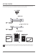
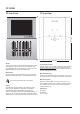
Sync In Word Clock
ForconnectionstoexternalclockviathestandardBNC
connector (see illustration above).
When several devices are connected in a chain and
synced via Word Clock, termination on the last device of
the chain is necessary.
As the System 6000 is expected to be the last unit in such
a chain (or the only), the factory default setting on the
System 6000 DSP card is: TERMINATED (75 Ohm).
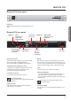
If you need to terminate the Word Clock signal elsewhere
in the chain you will need to un-terminate the System 6000
DSP card. To do this you must remove the DSP card from
the mainframe and remove the termination jumper:
• Switchoffthepoweranddisconnectmainpowercord.
• LoosenthetwoscrewsholdingtheDSPcardand
remove the card gently.
• RemovetheterminatingjumperneartheBNCplug.
• InsertthecardgentlyintheDSPslotandremount
the screws.
Pins connected via jumper : Terminated (75 Ohm).
Pins NOT connected via jumper : Not Terminated
Termination jumper
Dipswitches1to4shouldALWAYSbesettooff.
General Handling
When inserting or removing any modules, avoid touching
the circuit board by handling only the rear panel of the
module. To minimize the static potentials that can cause
damage to the electronic circuits, you should observe
precautionary grounding techniques such as touching a
grounded System 6000 Mainframe immediately before
inserting modules.
BNC
connector