Operation manual English
Table Of Contents Contents Table Of Contents................................................... 3 Important safety instructions.................................. 4 Introduction............................................................. 5 Getting Started....................................................... 6 Front And Rear....................................................... 7 DSP 6000 - Card And Connections........................ 8 Remote CPU..........................................................
Important safety instructions The exclamation point within an equilateral triangle is intended to alert the user to the presence of important operating and maintenance (servicing) instructions in the literature accompanying the product.
Introduction Thank you for purchasing the System 6000 and welcome to an endless world of opportunities. System 6000 comes in two basic versions: Reverb 6000 and Mastering 6000, each offering the best tools possible for effects and dynamics processing. System 6000 is a constantly evolving platform and will be continuously improved and kept up to date with new algorithms and new features.
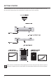
Getting Started This is an illustration of how to connect a standard System 6000 as it comes with one Mainframe and one TC Icon. We recommend reading through the entire Hardware & Installation section before operating. Please note that a crossed ethernet cable (supplied) must be used in this type of setup. When the system is connected to a HUB as a part of a major network non-crossed ethernet cables must be used (not supplied).
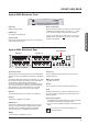
FrontPAGE And HEAD Rear Power Key Reset (countersunk) Switches power On/Off. Press and hold this button during boot to reset the frames IP address to the default setting: 192.168.1.xx*, - where “xx” is the last two digits in the frames serial number. PCMCIA slot For handling of preset banks. Power On LED During start-up this LED is red. When the unit is ready for use, the LED will turn green. * Note - if the frames serial number ends on “00”, the IP address will be: 192.168.1.
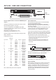
DSP 6000 - Card And Connections BNC connector Use the supplied cable to connect the AES/EBU Inputs/ Outputs. Cable type is twisted pair (12 pairs) with common screen. Recommended impedance: 110 Ohm. One end is equipped with an AES/EBU 25 pin DSub connector, the other end is equipped with four male XLR’s and four female XLR’s. Male XLR’s are marked with: Out - 1 to 4. Female XLR’s are marked with: IN- 1 to 4. Extension cables must be constructed according to AES/ EBU-3 standards.
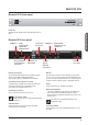
Remote PAGE HEAD CPU Remote CPU front panel Power Key HW & installation Switches power On/Off. Green LED indicates power on state. Remote CPU rear panel COM port 1 LAN 1 connection for setups with multiple frames PS-2 connection for PC keyboard and mouse Connection for TC Icon Connection for VGA monitor COM port 2 Ethernet/LAN connection for sw updates etc.
TC Icon TC Icon Rear 279 mm TC Icon Front 198 mm Screen The TC Icon screen is a touch-sensitive capacitive screen. The resolution is 640 x 480 16 bit color resolution. The touch calibration as well as brightness and colors can be adjusted/selected in the TC Icon Setup menu. Maintenance The touch screen must be cleaned only with a soft cloth slightly moistened with water or a mild detergent solution. Do not spray liquids directly on the screen. Faders The Faders are touch-sensitive.
HEAD Installing AdditionalPAGE I/O Cards Caution! The servicing instructions are for use by qualified personnel only. To reduce the risk of electric shock do not perform any servicing other than that in the operation instructions unless you are qualified to do so. Slot A I/O Cards Dip 1 on on off on Dip 2 off on on off Dip 3 off off off on Dip 4 off off off off Before mounting modules in your M6000, switch off the power and unplug the main power cable.
Updating System 6000 MKII Software Keeping your software updated System 6000 is a constantly evolving platform and updating software is a standard procedure to keep the system up-to-date. Depeding on your setup, software-updates can be done in a couple of different ways described on the following pages.
Updating System 6000 MKII Software Updating Remote CPU MKII software Update Remote CPU 2 HW & installation TC ICON MKII REMOTE CPU MKII LAN 2 Standard Ethernet cable INTERNET Remote CPU MKII software is updated directly via the internet.
Update Mainframe SW Updating System 6000 MKII Software Updating Mainframe 6000 MKII software TC ICON EDITOR on PC OR MAC M6000 MKII X-Coupled Ethernet cable - Download and install TC Icon Editor on a Mac or a PC - Download Frame, DSP & Net software to a folder on your computer. PC example: Create a folder in the root directory (C), and call the folder s6kupdate. The path for this folder is then “C:\s6kupdate”. Unzip and place the Frame, DSP & Net software in this folder.
Updating System 6000 MKII Software Advanced setup - Central Server setup for software for update and preset handling “TC NETWORK” (Static IP) - STUDIO A “TC NETWORK” (Static IP) - STUDIO B M6000 MKII 8 x XLR FOR DIGITAl I/O LAN 1 8 x XLR FOR DIGITAl I/O LAN 2 M6000 MKII TC ICON EDITOR on PC OR MAC TC ICON MKII Static IP 10.10.10.1 Standard Ethernet Cables Static IP 10.10.10.2 Static IP 10.10.10.3 Standard Ethernet Cable REMOTE CPU MKII Static IP 10.10.10.2 DHCP e.g. 192.168.1.
Updating System 6000 MKII Software Central Server (MotherShip) setup This is a typical setup in larger studio facilities with several rooms, where you place software updates and e.g. a preset vault on a central server/computer in a shared folder. The illustration on the previous pages shows two studios and a central server with internet access. LAN 1 TC Network connects: - Local System 6000 Mainframes - Local Remote CPU LAN 1 - E.g.
Preset Vault on Central Server In larger studio facilities with several studios, preset banks and automation presets can be stored on a central server in a setup similar to the one described on the previous pages. We recommend creating two seperate shared folders on the server. One for preset banks and one for automation presets. In the examples below we use the following folder names: Automation Presets Automation presets are stored and recalled directly to and from a shared folder on the central server.
Network Basics Subnet Mask & TCP/IP addresses The Subnet Mask is a number that defines a group of computers (or Icons/Mainframes) connected to the network. All units in the group must have the same Subnet Mask. The System 6000 Subnet Mask is by default 255.255.255.0 The TCP/IP address is unique to each unit connected in the network. An IP address consists of 4 numbers separated by a “.” Example: 192.168.1.1 The first three numbers (e.g. “192.168.
Network Basics Shared folders PC - basics When sharing a folder on Windows XP/VISTA/WIN7 you have to make sure that the user of the TC Icon Remote CPU MKII has rights to access read/write in the share folder.
Network Basics Windows 7 note For succesfully sharing a folder on Win7 x86/x64 you have to setup sharing rights for the folder(any share) on the machine. Shared folders Mac - basics On Mac computers shared folders are setup in System Preferences - Shared. - Open Network and Sharing Center by clicking the Start button , clicking Control Panel, clicking Network and Internet, and then clicking Network and Sharing Center.
Updating TC Icon/Remote CPU MK II From a Central Server There are two ways of updating the software Updating directly from the Internet - if the TC Icon Remote CPU MKII’s LAN2 (Internet) connection is connected directly to the internet, the software can be updated directly. See explanation on page 14. Updating from a Central Server - The software is downloaded, placed in a shared folder on a central server and updated from there.
TC Icon Editor Installation The TC Icon Software Editor for PC and Mac is a fully operational software version of the TC Icon Remote for the System 6000. The software is free to download via www. tcelectronic.com Installation - PC System Requirements • Windows 2000, NT, XP, Vista or 7 • 1 GB RAM • INTEL/AMD 1.66 GHz Updating/installing the TC Icon Software Editor • Go to: http://www.tcelectronic.com/reverb6000software.asp - or http://www.tcelectronic.com/mastering6000software.
Savvy WI-fI networking for System 6000 Introduction PC Setting up a Wi-Fi connection in your System 6000 network is basically making an access point in the network. For this you can use any router with Wi-Fi or access point you can buy today, but check that it has the features you need before buying. The TCP/IPV-4 protocol has to be set for “Use the following IP address” and do only enter “IP address” and “Subnetmask” (In this case as described above I would set IP for 192.168.1.150 and Subnet mask 255.
Basic Operation List of connected units Introduction Engine Structure Accessing a Mainframe Engine Resources This section of the manual is a general introduction on how to operate System 6000 via the TC Icon. The basic System 6000 consists of a Mainframe with a DSP card and up to three I/O cards, plus a TC Icon remote with Remote CPU. Several mainframes as well as several TC Icons can be hooked up at the same time via a standard Local Area Network (LAN).
PAGE HEAD Basic operation Library, Frame & Engine select Tabs Function Select Tabs Operating Levels The Library-Recall page illustrated in Fig.3 leads to explanation of the “operating levels” in the System 6000. We differentiate between 3 levels of presets: Scene, Routing and Engine levels. • SCENE This is the most extensive selection you can make. It includes all four Engine algorithms as well as Physical and virtual Engine connections. A Scene recall can be compared to a “total recall.
Library - Recall Operation Level Tabs Bank Selectors Search Library, Frame and Engine selectors Function Select Tabs Fader Group Selector Parameter Fader values present in the last modified Engine. Library Recall On the Library Recall page the following banks are available for recall operations.
PAGEFilter HEAD The Wizard And Algorithm Introduction To easily find the perfect preset for your application among the vast amount of presets available in the System 6000, we have added a Wizard function. Basically the Wizard allows you to set up a few criteria and thereby narrow down the pool of presets to select from. All Reverb Factory presets are marked with Wizard category-tags. When storing User presets you can assign a Wizard category tag yourself to each preset.
The wizard and algorithm filter Type This is where you make the most detailed selection of presets to choose from. Algorithm Filter • Specify from which types of presets you would like to recall. Types varies depending on the selected Wizard Category selected on the Mode page. • Pressing the top field in each column will select or deselect the entire column. To access; press the Algo tab on the Wizard “main-page”. Operation • Now press OK and and you will return to the Wizard “main-page” (see below).
PAGEStore HEAD Library Operation Level Tabs Name Field Library, Frame and Engine selectors Press WIZARD to add Wizard tags to presets. Function Select Tabs Fader Group Selector On the Store page you may store Scene, Routing and Engine presets. operation Library Store - Scene, Routing or Engine presets Parameter Fader values present in the last modified Engine. Wizard • Press to enter the Wizard page. Storing a Preset • Press the Store tab and select Scene, Routing or Engine 1-4.
Bank And Naming Display Library - Bank Via the Library Archive page you can copy Scene, Routing and Engine banks to and from a PCMCIA card and to/from a folder on your computer if you are using the TC Icon software Editor. A 512kB PCMCIA card can hold: 500 Engine presets in 5 banks of 100 presets 250 Routing presets in 5 banks of 50 presets 250 Scene presets in 5 banks of 50 presets File Folder Enter the path to a folder (or shared folder) on a computer or server.
Library - Delete PAGE HEAD Library, Frame and Engine selectors Function Select Tabs Parameter Fader values present in the last modified Engine. operation Fader Group Selector Library - Delete For convenience it is possible to “clean up” the User bank by deleting individual presets. Deleting a Preset • Press Delete (side tab) and select level by pressing Scene, Routing or Engine. • Select decade and preset location and press the Delete button.
Frame Page Frame - Routing To distribute a single Output of an Engine to several physical Outputs: • Route the Engine Output to a physical Output. • Route the same Engine Output through a passive channel of an algorithm loaded in another Engine. E.g. channels 7 and 8 of the Toolbox-5.1. When routing an Engine Output to an Engine Input with the M5000 frame and no TC Icon, the Engine Input channel number must match the Engine Output number from where the signal originates. E.g.
PAGE- HEAD Frame System Main Frame - E1 to E4 Locked Clock Rate The Clock Rate to which the Mainframe is currently locked. If the incoming Sample Rate is +/- 0.2% away from 32, 44.1, 48, 88.2 or 96kHz the Sample Rate will be shown with an added “!” to indicate that the Sample Rate is inaccurate. Color indications Red color in Clock Status field: External clock source is selected but no lock is achieved. Check connections and external device. This is a critical alert and no signal will be processed.
Frame PAGE HEAD system - main SMPTE Bank Mode The Bank mode settings determine the destination bank of the received program change on the specified MIDI channels. Normal mode: This mode requires that the external sending MIDI device can send both Controller 0 and 32 in addition to MIDI program changes. This is an essential feature to recall presets from a device holding more than 128 preset location.
MIDI Control Page MIDI Dump Page On MIDI Control Page the following options are available: Pressing these command buttons will dump the current settings as SysEx messages to the MIDI Out port of the Mainframe. Read Program Change Select whether the Frame should read incoming program changes or not. If connected to a MIDI sequencing device it is then possible to store/recall current settings as part of your sequencing project or as backup handling via MIDI.
PAGE HEAD Frame system - main External MIDI Control - of Fader Parameters From software version 2.5, all fader assignable parameters can be remote controlled via MIDI Control Change Messages. To be able to control Faders you must create a dedicated Fader User Group holding these parameters. Page 20 in this manual section explains how to create User Fader Groups.
PAGE- HEAD Frame system main Setting up Make sure to select MIDI channel settings corresponding to the channels your external controller is using for each Engine. This is setup in the MIDI Setup page. How to record/playback MIDI data into/from DigiDesign Protools 5.x ? Recording • On the TC Icon go to the Frame/System/Main/MIDI page, and set up the Send/Receive parameters as follows: Send CC Receive CC The following example explains how to avoid this on a Protools System.
PAGE HEAD Frame system - main Net Error Indication Software versions Current installed software versions. Network Identifier Press the field “Network Identifier” to enter a name for the Mainframe. This is the global TC network name for the frame. By giving the frame a specific name it will be easier to identify the frame when hooked up in a network with several frames. IP- address The IP address for the Mainframe.
Frame System PAGE HEAD - I/O Via the I/O page the following operations are handled: • Settings for the DSP card • Settings for up to three I/O cards • Labeling of all physical Input and Output channels I/O - DSP Basic operation If more than one mainframe is connected: • Press the Icon symbol in the upper left corner to enter the Select & Setup pages • Select which mainframe you wish to setup • Press the Icon symbol once again and and select System - I/O as illustrated above I/O - SETUP The following Set
PAGE HEAD Frame system - I/O I/O - Slot A, B & C This is where you setup card specific parameters. Parameters are only available when a I/O Card is detected. For the ADA 24/96 card the following parameters can be set. Output, pin 2 selected Pin 2 hot, pin 3 connected to reference (shield) at the Input of downstream device. In this mode pin 3 acts as a reference Input for the ADA2496 Output stage and should not be left un-terminated.
Frame system PAGE HEAD - I/O “Bright” filter These filters are something entirely different: Ultra-short impulse response, linear phase and quite a bit of deliberate aliasing produces a “digital” and slightly aggressive sound adding plenty of top-end life to e.g. Rock and Techno recordings, or giving you the feeling of air you need when you are mastering a somewhat dark sounding source material.
PAGE HEAD Frame system - Licenses Licenses The System 6000 holds numerous algorithms as a part of the standard package. Various other algorithms are available. These algorithms require purchasing of Licenses. The License types and their status (active/inactive ) available with the installed software are listed under “License Type”. (see above) To try out one or more of the licenses a time limited Demo Key can be achieved by contacting TC Electronic. Press the Get Demo Key and follow the instructions.
EnginePAGE Edit HEAD Page Name of the currently recalled preset Library Frame and Engine Selectors Overflow Indication Input Meters Parameter Pages Link key Output Meters Fine Adjust Mode The Engine 1-4 Edit Pages This is where you edit algorithm parameters.Parameters in several algorithms are distributed on different pages. As illustrated above the MD 5.1 has 6 pages: Main, Setup, Expander, Compressor, Limiter and Output.
PAGE HEAD Icon Setup Page Icon User Interface Sticky Clip Go to the Select & Setup pages pressing the TC Icon key in the upper left corner. Meter Clip Indicators If the Sticky Clip function is activated the Internal Overload LED on the Frame Routing page will stay lit once activated until Reset Clip on the Frame Routing page is pressed. Press SETUP (upper tab) and UI (side tab) to enter the setup page for the TC Icon display.
PAGESMPTE HEAD Auto Edit Page Cursor The white triangular cursor always indicates the current clock position in relation to the Event List. Event Parameters For each Event the following parameters are available. Time Device Event - indicates the SMPTE time at which the Event takes place. indicating on which Device Mainframe the Event is taking place. Device numbers 1-8, corresponds to the Device position at the Select page. states the occurring Event at the given time.
PAGE HEAD Smpte Step/Adjust Range: Frame, 1 Second, 10 Seconds, 1 min., 10 min. or 1 hour. Use the Step parameter to select Adjust range and the Adjust parameter to increase/decrease the time. Device This parameter selects which Mainframe connected to the LAN you are working on. Device numbers 1-8, corresponds to the Device position at the Select page. Preset Type Selects whether the preset Event you are working on is a Scene, Routing, Engine or a System preset.
TC Icon Software Editor HEAD PAGE The TC Icon Software Editor is a fully operational software remote control for the System 6000 Faders at bottom All functions available via the TC Icon hardware version are also available via the Software Editor. A network adapter must be installed in your computer for connection to a Mainframe. To install the TC Icon Software Editor, please follow the instructions in the Hardware & Installation chapter.
Controlling more than 8 Frames It is possible to control up to 32 System 6000 MKII Mainframes using four instances of the TC Icon Editor on a PC*. To do so, follow these steps: - Place the TC Icon exe file on your desktop if it is not already there. - Create three shortcuts to the Icon.exe file and rename each instance. E.g. Icon 1, Icon 2 etc. - Then right-click on each shortcut and enter the following lines in “Target”: “C:\Documents and Settings\MYPC\Desktop\Icon.
PAGE HEAD Room Simulation For Multichannel Music And Film Introduction For more than 10 years TC Electronic has put considerable research resources into perfecting digital room simulation. Our achievements have been made possible by combining scientific room models with intensive listening tests and perceptual adjustments. This is also the case with the VSS5.1 room simulator which is the crown jewel of the algorithms included with System 6000.
Room simulation for multichannel music PAGE andHEAD film In many studios, one good reverb is used to render the basic environment of a particular mix. One aux send, set at different levels on the different channels, is used to obtain depth and some complexity in the sound image. To obtain a sound image of a higher complexity and depth, several aux’s and reverbs have normally been used. for home (110 degree surround speakers) and theatre (side array surround speakers) reproduction.
PAGE HEAD Room simulation for multichannel music and film • The system should not be limited to simulating natural acoustics: Often quite unnatural reverb effects are desired, e.g. for pop music or science fiction film effects. • The system should be able to render the simulation via a number of different reproduction setups, e.g. 5.1, 7.1, stereo etc.
PAGE Room simulation for multichannel music andHEAD film 4 months, we will have more real life experience with the system. If integrated positioning is used with multi-source room simulation, our experiments have already shown how much there is to gain in terms of realism and working speed. But even with the less radical additive approach, virtual rooms may be rendered more convincingly with multi-source simulators.
Sample PAGE HEAD Rate Conversion Filters - ADA 24/96 Sample Rate Conversion Filters Introduction The Delta-Sigma Converters of the ADA 24/96 operate at 6.144MHz (48/96kHz sample rate) or 5.6448MHz (44.1/88.2kHz) at the ends facing the analog world. But the processing, transmission and storage of high-quality audio material are often done at 48 or 44.1kHz.
Sample rate conversion filters PAGE - adaHEAD 24/96 Fig. 2 Fig. 3 illustrates how attenuation is performed just above FS/2 when operating at 48kHz sampling rate. As shown in fig. 4 alias components will be reflected around FS/2 and will disturb the high but still audible frequencies. Fig.
Clock PAGE HEAD And Synchronization In System 6000 By Christian G. Frandsen Introduction This document will discuss the clock, synchronization and interface design of TC System 6000 and deal with several of the factors that must be considered when using a digital studio. We will go through different aspects in this area e.g. • What is jitter, what causes it and how is it removed on System 6000. • Measurements comparing a conventional clock design to that of System 6000.
Clock and synchronization in system PAGE HEAD 6000 Causes of Jitter There are several ways that jitter find it’s way into a digital studio setup. Noise induced on cables A digital receiver typically detects a rising or a falling edge on a digital signal at approx. halfway level. Due to finite rise/fall times on the signal, noise then can disturb the detection so the receiver detects the edges imprecisely.
PAGE HEAD Clock and synchronization in system 6000 How to detect interface jitter. The typical way to investigate interface jitter is by measuring the clock variations directly on the digital signal. There are devices made specifically for interface testing. The way they usually work is by applying a PLL circuit like the ones used for jitter rejection (see The clock design on System 6000) and then measure the amount that has been stopped by the PLL.
Clock and synchronization in system PAGE HEAD 6000 System 6000 technical specifications regarding the clock circuitry: Figure 5 Zoomed picture of the jitter rejection filter. Lock range Jitter rejection filter (4’Th order filter): < -3dB @ 50 Hz < -69dB @ 500 Hz < -100dB @ 1.4 kHz Jitter gain: < 1 dB @ 2Hz Jitter rejection at external sample rates: 30 to 34 kHz, 42.5 to 45.6 kHz, 46.5 to 48.5 kHz, 85 to 91 kHz, 93 to 97 kHz. Internal sample rates: 96 kHz, 88.2 kHz, 48 kHz and 44.1kHz.
PAGE HEAD Clock and synchronization in system 6000 Measurements on System 6000 As mentioned before the higher frequency in the program signal and the higher level the more sensitive it is to jitter on the sampling clock. Therefore the measurements in this document uses a 20 kHz sine at -1 dBFS and all measurements are done at 48 kHz sample rate. The measurements are done on the DA converter on the ADA24/96 card and the test system is Audio Precision System 2 Cascade. slave to the digital input.
Clock and synchronization in system PAGE HEAD 6000 Figure 10 Zoomed (frq. only). System 6000 and conventional design in slave-mode. Wide band jitter applied. Synchronization Synchronization: The digital signal, word clock or AES 11. There are several ways to obtain synchronization in a setup: Using a digital signal (carrying audio), a digital signal (not carrying audio) or a word clock. • Digital signal (carrying audio).
Clock PAGE HEAD and synchronization in system 6000 period away from the signal on input 1. If the phase of a signal (including two audio channels) is above the limit, the current sample in this signal can be interpreted as the previous or the next sample and this will add a delay to these specific two audio channels. A summing of the signals later in the setup (e.g. electrically or acoustically) will result in a potential audible phase error.
Clock and synchronization in system PAGE HEAD 6000 ADAT interfaces are typically more sensitive to sub sample delays or phase offsets than AES interfaces. System 6000 technical specifications regarding in and output phase: Digital Output Phase: Input Variation Before Sample Slip: < 3 % of sample period +27 % / -73 % of sample period Literature: [1] Jitter: Specification and Assessment in Digital Audio Equipment by Julian Dunn. Presented at AES 93rd Convention, October 1992 Available at www.nanophon.
PAGE HEAD License Agreement TC ELECTRONIC SOFTWARE LICENSE AGREEMENT System 6000 Additional Software PLEASE READ THIS LICENSE CAREFULLY BEFORE USING THE SOFTWARE. BY PROCEEDING AND USING THE SOFTWARE, YOU ARE AGREEING TO BE BOUND BY THE TERMS OF THIS LICENSE. IF YOU DO NOT AGREE TO THE TERMS OF THIS LICENSE, PROMPTLY RETURN THE UNUSED SOFTWARE TO THE PLACE WHERE YOU OBTAINED IT AND YOUR MONEY WILL BE REFUNDED. 1. License.
License agreement PAGE HEAD End Users License Agreement (EULA) for TC ICON OS (Operating System) Termination contained in the TC Electronic A/S embedded system: TC ICON/Remote CPU 6000. Without prejudice to any other rights, TC Electronic A/S may terminate this license if you fail to comply with the licensing terms. In such event, you must destroy all copies of the TC ICON OS and all of its component parts. The TC ICON operating system is based on Microsoft NT.
PAGE HEAD Specifications - Mainframe 6000 MKII Technical Digital Inputs and Outputs Connectors: Formats: Word clock input: Internal sample rate: Internal clock precision: Jitter rejection at external sample rates : Rejection filter (4’th order) : Rejection filter peak (jitter gain) Intrinsic interface jitter : Digital output phase : Input variation before sample slip : Output Dither: Processing Delay: Frequency Response DIO: PCMCIA Interface Connector: Standards: Card Format: PC Card, 68 pin type 1 cards
Technical Specifications - TC Icon & Remote PAGE HEAD CPU Display Type: Touch screen: Faders: Connection: EMC Complies with: Safety Certified to: Environment Operating Temperature: Storage Temperature: Humidity: General Finish: Remote CPU 6000 mk II 6,5” TFT active matrix color LCD display, 640 x 480 pixels resolution. High luminance (300 cd/m2, typ.