Model 811, 813, 819, 821 Series Auto Lift Gas Grills Original Operating Instructions 073625-M 9/15/10 (Original Publication) (Updated 4/19/13)
Complete this page for quick reference when service is required: Taylor Distributor: Address: Phone: Service: Parts: Date of Installation: Information found on data plate: Model Number: Serial Number: Electrical Specs: Voltage Cycle Phase Maximum Fuse Size: Amps Minimum Wire Ampacity: Amps Part Number: E September, 2010 Taylor All rights reserved. 073625-M The word Taylor and the Crown design are registered trademarks in the United States of America and certain other countries.
Table of Contents Section 1 To the Installer . . . . . . . . . . . . . . . . . . . . . . . . . . . . . . . . . . . . . . . . . . . . 1 Installer Safety . . . . . . . . . . . . . . . . . . . . . . . . . . . . . . . . . . . . . . . . . . . . . . . . . . . . . . . . 1 Site Preparation . . . . . . . . . . . . . . . . . . . . . . . . . . . . . . . . . . . . . . . . . . . . . . . . . . . . . . . 1 Electrical Connections . . . . . . . . . . . . . . . . . . . . . . . . . . . . . . . . . . . . . . . . . . . .
Table of Contents - Page 2 Section 6 Operating Procedures . . . . . . . . . . . . . . . . . . . . . . . . . . . . . . . . . . . . . 17 Daily Opening Procedures . . . . . . . . . . . . . . . . . . . . . . . . . . . . . . . . . . . . . . . . . . . . . . 17 Loading Store Menu Items To USB . . . . . . . . . . . . . . . . . . . . . . . . . . . . . . . . . . . . . . 23 Loading Menu Items From USB . . . . . . . . . . . . . . . . . . . . . . . . . . . . . . . . . . . . . . . . . 24 Operating Procedures .
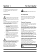
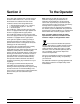
Section 1 To the Installer The following are general installation instructions. For complete installation details, please see the checkout card. This unit has many sharp edges that can cause severe injuries. Installer Safety Site Preparation Review the area where the unit will be installed before uncrating the unit. Make sure all possible hazards to the user or equipment have been addressed. In all areas of the world, equipment should be installed in accordance with existing local codes.
Installation CAUTION: THIS EQUIPMENT MUST BE PROPERLY GROUNDED! FAILURE TO DO SO CAN RESULT IN SEVERE PERSONAL INJURY FROM ELECTRICAL SHOCK! WARNING: Improper installation, adjustment, alteration, service or maintenance can cause property damage, injury or death. Read the installation, operating and maintenance instructions thoroughly before installing or servicing this equipment.
Section 2 To the Operator The Taylor grills included in this manual consist of the base model numbers 811, 813, 819, and 821. Prefix letters were added to the base model numbers to denote minor design differences: C = Standard Platen Length (17.5” / 445 mm) L = Longer Platen Length (21” / 533 mm) G = Grooved Option The models 811 and 813 are 36” (914 mm) grills. The 811 is equipped with three upper platens and the 813 is equipped with two upper platens.
Section 3 Safety We, at Taylor Company, are concerned about the safety of the operator when he or she comes in contact with the grill and its parts. Taylor has gone to extreme efforts to design and manufacture built-in safety features to protect both you and the service technician. As an example, warning labels have been attached to the grill to further point out safety precautions to the operator.
IMPORTANT: DO NOT use a water jet or spray excessive water on or anywhere near the grill. Failure to follow this instruction may result in serious electrical shock and cause permanent electrical and mechanical damage to internal parts. DO NOT use cold water or ice to cool the upper platen or the lower cook surface.
These instructions are valid only if the country code symbol appears on the appliance. If the symbol does not appear on the appliance, refer to the technical instructions which give the necessary instructions for adapting the appliance to the utilization conditions of that country. Access to the service area of the unit is restricted to persons having knowledge and practical experience with the appliance, in particular as far as safety and hygiene are concerned.
Section 4 Operator Parts Identification C811 Exploded View Figure 1 ITEM DESCRIPTION PART NO. ITEM DESCRIPTION PART NO. 1 CAN A.-GREASE X80925 12 NUT-JAM 1-1/2-12 (2 PCS) 073594 2 SLIDE-GREASE CAN LEFT 069936 13 CASTER-5" 7-5/8 STEM 078377 3 PANEL-SIDE-UPPER *LEFT 073990 14 CASTER-GRILL 5” SWIVEL LOC 073240 4 SCREW-10-32X3/8 SLTD TRUS 024298 15 KIT A.-GRILL CONTROL GEN X73474-SER 5 PANEL-SIDE-LOWER *LEFT 073992 16 SWITCH-ROCKER-DPST-10A 076989-WP KIT A.
L811 Exploded View Figure 2 ITEM DESCRIPTION PART NO. ITEM DESCRIPTION PART NO. 1 CAN A.-GREASE X80925 12 NUT-JAM 1-1/2-12 (2 PCS) 073594 2 SLIDE-GREASE CAN LEFT 069936 13 CASTER-5" 7-5/8 STEM 078377 3 PANEL-SIDE-UPPER *LEFT 073990 14 CASTER-GRILL 5” SWIVEL LOC 073240 4 SCREW-10-32X3/8 SLTD TRUS 024298 15 KIT A.-GRILL CONTROL GEN X73474-SER 5 PANEL-SIDE-LOWER *LEFT 073992 16 SWITCH-ROCKER-DPST-10A 076989-WP KIT A.
C813 Exploded View Figure 3 ITEM DESCRIPTION PART NO. ITEM DESCRIPTION PART NO. 1 CAN A.-GREASE X80925 13 CASTER-5" 7-5/8 STEM 078377 2 SLIDE-GREASE CAN LEFT 069936 14 073240 3 PANEL-SIDE-UPPER *LEFT 073990 CASTER-GRILL 5" SWIVEL W/LOCK 4 SCREW-10-32X3/8 SLTD TRUS 024298 15 KIT A.-GRILL CONTROL GEN X73474-SER 5 PANEL-SIDE-LOWER-LEFT 073992 16 SWITCH-ROCKER-DPST-10A 076989-WP 17 BUTTON-OPERATOR-BLACK 076012 18 BUTTON-OPERATOR-RED 076011 19 COVER A.
L813 Exploded View Figure 4 ITEM DESCRIPTION PART NO. ITEM DESCRIPTION PART NO. 1 CAN A.-GREASE X80925 12 NUT-JAM 1 1/2-12 STEEL 073594 2 SLIDE-GREASE CAN LEFT 069936 13 CASTER-5" 7-5/8 STEM 078377 3 PANEL-SIDE-UPPER *LEFT 073990 14 SCREW-10-32X3/8 SLTD TRUS 024298 CASTER-GRILL 5" SWIVEL W/LOCK 073240 4 5 PANEL-SIDE-LOWER-LEFT 073992 15 KIT A.
C819 Exploded View Figure 5 ITEM DESCRIPTION PART NO. ITEM DESCRIPTION PART NO. 1 CAN A.-GREASE X80925 13 NUT-JAM 1 1/2-12 STEEL 073594 2 SLIDE-GREASE CAN LEFT 069936 14 CASTER-5" 7-5/8 STEM 078377 3 PANEL-SIDE UPPER-LEFT 073990 15 073240 4 SCREW-10-32X3/8 SLTD TRUS 024298 CASTER-GRILL 5" SWIVEL W/LOCK 5 PANEL-SIDE-LOWER-LEFT 073992 16 KIT A.-GRILL CONTROL X73474-SER 6 SLIDE-GREASE CAN RIGHT 069935 17 PANEL A.-FRONT-LOWER X69660 7 PANEL A.
L819 Exploded View Figure 6 ITEM DESCRIPTION PART NO. ITEM DESCRIPTION PART NO. 1 CAN A.-GREASE X80925 13 NUT-JAM 1 1/2-12 STEEL 073594 2 SLIDE-GREASE CAN LEFT 069936 14 CASTER-5" 7-5/8 STEM 078377 3 PANEL-SIDE UPPER-LEFT 073990 15 073240 4 SCREW-10-32X3/8 SLTD TRUS 024298 CASTER-GRILL 5" SWIVEL W/LOCK 5 PANEL-SIDE-LOWER-LEFT 073992 16 KIT A.-GRILL CONTROL X73474-SER 6 SLIDE-GREASE CAN RIGHT 069935 17 PANEL A.-FRONT-LOWER X69660 7 PANEL A.
C821 Exploded View Figure 7 ITEM DESCRIPTION PART NO. ITEM DESCRIPTION PART NO. 1 CAN A.-GREASE X80925 13 PANEL-SIDE-LOWER-RIGHT 073991 2 SLIDE-GREASE CAN LEFT 069936 14 NUT-JAM 1 1/2-12 STEEL 073594 3 PANEL-SIDE UPPER-LEFT 073990 15 CASTER-5" 7-5/8 STEM 078377 4 SCREW-10-32X3/8 SLTD TRUS 024298 16 073240 5 PANEL-SIDE-LOWER-LEFT 073992 CASTER-GRILL 5" SWIVEL W/LOCK 6 PANEL A.-LIGHT X80626 17 KIT A.-GRILL CONTROL X73474-SER 7 PANEL A.
L821 Exploded View Figure 8 ITEM DESCRIPTION PART NO. ITEM DESCRIPTION PART NO. 1 CAN A.-GREASE X80925 13 PANEL-SIDE-LOWER-RIGHT 073991 2 SLIDE-GREASE CAN LEFT 069936 14 NUT-JAM 1 1/2-12 STEEL 073594 3 PANEL-SIDE UPPER-LEFT 073990 15 CASTER-5" 7-5/8 STEM 078377 4 SCREW-10-32X3/8 SLTD TRUS 024298 16 073240 5 PANEL-SIDE-LOWER-LEFT 073992 CASTER-GRILL 5" SWIVEL W/LOCK 6 PANEL A.-LIGHT X80626 17 KIT A.-GRILL CONTROL X73474-SER 7 PANEL A.
Accessories Figure 9 ITEM DESCRIPTION PART NO. 1 SHEET-RELEASE - BOX OF 9 (C811, C813, C819, C821) 073442 *2 RETAINER-SHEET RELEASE (RETENTION BAR) (C811, C813, C819, C821) 072845 **3 CLIP-RELEASE MATERIAL W/TAB 072673 4 SCRAPER-TEFLON WIPER 075887 5 STRIP-REPLACEMENT 075888 ITEM DESCRIPTION PART NO. ***6 HOLDER-CLEANING 073736 ***7 PAD-CLEANING 073737 CLEANER-STERA SHEEN (CASE OF 6, 1 QT.
Section 5 Important: To the Operator Note: The Model 811 three platen grill has been selected for illustration purposes.
Section 6 Operating Procedures The three platen Model L811 has been selected to illustrate the step-by-step procedures. For grills equipped with less than three platens, perform the following steps as appropriate for your grill platen configuration. Step 2 Hook the release sheet retainer on the release sheet shoulder screws at the top of the upper platen. Daily Opening Procedures Before operating the grill, the release sheets must be installed on the upper platens.
Step 4 Place the release sheet clips over the release sheet. Press them into place over the release sheet bar at the top of the platen. Step 6 Repeat steps 1 through 5 for the remaining upper platen(s). Note: Temperature checks should only be conducted with the release sheets removed. Replace the release sheet when: S Cleaning procedures fail to remove all buildup and product sticks to the release sheet.
Care of Release Sheets IMPORTANT! Clean the release sheets using the grill cleaning pad and holder identified on page 15 ONLY. Using any other pad and holder will damage the release sheets. DO NOT: S DO NOT fold or crease. Figure 18 Note: Contact your local Taylor Distributor to purchase the correct grill cleaning pad and holder. (See page 15.) Figure 17 S DO NOT touch with sharp objects, grill scrapers, or abrasive pads. S DO NOT place under other equipment or objects.
Note: If an ignition failure fault occurs upon start up, press the center of the control. The control will display “OFF”. Refer to problem #2, items a, b, and c of the Gas Grill Troubleshooting Guide on page 42. After five minutes has elapsed, press the menu key again. If the ignition failure fault was not resolved, please call your authorized service technician. The control will display the word “INITIALIZATION” for five seconds and then will enter the OFF mode, displaying the message “OFF”.
Step 3 The PROGRAM MODE screen will appear. Programming Menu Items To enter the Program Mode, the grill control must be in the OFF or IDLE mode. Step 1 Press and hold the PROGRAM key for approximately five seconds to enter the Program Mode. Figure 26 UNITS Key The UNITS key is used to select either English or metric units of measure. The UNITS key toggles between F and C with each key press. Figure 24 ADJUST VOLUME Key Step 2 The PASSWORD screen will appear.
To edit a menu item, press the menu item key to bring up a virtual keyboard. Type in the desired name (up to 8 characters per line) and then press the “X” key to return to the previous screen. MENU EDIT Key The MENU EDIT key is used to program a menu item. When the MENU EDIT key is pressed, the following screen will display. Figure 30 ACTIVE: YES or NO. This key displays the current selection. Pressing the key toggles to the opposite selection.
MULTIPLE TIMING FUNCTIONS: There is one timing function for clam items and a maximum of 3 timing functions for each flat menu item. Each function has a set of parameters associated with it. The function currently associated with the menu item is displayed. Pressing either function 1, function 2, or function 3 will bring up the next function in the list. The functions provided are: S S S VIEW HELP Key The View Help key is not functional at this time (future development).
Step 5 Press the MENU EDIT key. Step 8 Remove the USB flash drive from the USB port and reinstall the USB cable cap on the USB connector. Note: Grills built prior to serial number M1035495 will require the front control panel be reinstalled. Loading Menu Items From USB Once the proper software is loaded on the USB flash drive, the next control board can be programmed from the USB flash drive. Figure 34 Step 1 Repeat Steps 1 through 5 from “Loading Store Menu Items to USB.
Patty Placement & Removal Placement procedures of meat products must be followed on the grill. The meat must be placed on the lower grill surface from front to back. When the cook cycle is complete, the upper platen will raise. Patties must be removed immediately after the upper platen has been raised to the OPEN position and after the meat has been seasoned. Patties are generally placed two at a time from front to back of grill and right to left.
Patty Placement & Removal (continued) C Series Grills (Shorter Platen Version) 130312 Operating Procedures 26 Model 811, 813, 819, 821 Series
During the cooking cycle, the display will show the name of the current menu item, “REMOVE IN”, and the time remaining until the product should be removed. Operating Procedures Cooking Product Step 1 Select the menu item to be cooked. The grill is at the correct temperature if the control does not display any temperature statements and the grill temperature indicators are green. Step 2 Quickly place the product on the lower grill surface, from front to back.
Standby Procedures Menu Parameters Whenever the grill is idle and product is not being cooked, the upper platen must be placed in the STANDBY position. To view the settings and actual temperatures for the current item, press and hold the menu item key a minimum of 5 seconds. The screen will display the cook time, gap setting, temperature set points and actual temperature readings for each zone for that menu item.
Step 2 Use the wiper squeegee to clean the release sheet on the upper platen. Hold the handle at a slight upward angle. Use a downward motion to clean the sheet. (Note: Do not use excessive pressure when wiping the release sheet with the squeegee, as this can scratch or tear the release sheet.) Step 4 Use the grill cloth to clean the back splash plate and the bullnose areas as needed during operation.
Step 2 Press the CLEAN key. When the cook surfaces reach the proper temperature for cleaning, an alarm will sound and the message “READY TO CLEAN” will be displayed. Step 4 Put on heat-resistant gloves. Figure 47 CAUTION: The upper platen surface and release sheets are very hot. To prevent burn injuries, use extreme care. Figure 45 Step 3 Press the RAISE button to cancel the alarm. Step 5 Wipe the exposed surface of the release sheets with a clean, sanitizer-soaked grill cloth.
Step 6 Remove the release sheet clip, release sheet retainer, and the release sheet. Take these parts to the sink to be washed and rinsed. Step 10 Scrape the lower grill surface with the grill scraper, from front to back. Figure 51 Step 11 Use the wiper squeegee to push residual grease into the grease cans. Figure 49 Step 7 Repeat steps 1 through 6 for the remaining upper platen(s). Step 8 Wash and rinse the clips and retainers in the sink. Set them aside for future use.
Step 13 Using an approved high temperature grill cleaner, pour approximately 3 oz. (90 ml) onto each 12” (305 mm) cook zone. Step 17 Apply grill cleaner to the bottom of the platen handles. Figure 54 Step 14 Firmly attach the non-abrasive pad to the grill cleaning pad holder. Figure 56 IMPORTANT! Use the grill cleaning pad and holder identified on page 15 ONLY. Using any other pad and holder will damage the release sheets. DO NOT use metal scrapers, abrasive pads, screens, or wire brushes.
Step 19 Apply grill cleaner to the back side of the upper platens. Step 25 Lightly scrub the platen surfaces. Figure 59 Step 26 Lightly scrub the back side of the upper platens. Figure 58 Step 20 Apply grill cleaner to the outer edges of the right and left platens. Step 21 Press the STANDBY button twice to lower one of the platens. Figure 60 811 Only: Press the STANDBY button twice to lower the center platen. Apply grill cleaner to both sides of the center platen.
Step 32 With a clean, sanitizer-soaked grill cloth, rinse the bottom of the platen handles, and the front, sides, and back of the platen surfaces. Step 34 Press the STANDBY button twice to lower one of the platens. 811 Only: Press the STANDBY button twice to lower the center platen. With a clean, sanitizer-soaked grill cloth, rinse both sides of the center platen. Step 35 With a clean, sanitizer-soaked grill cloth, rinse the inner edges of the right and left platens.
IMPORTANT! To avoid damaging the grill: DO NOT use a jet of water to clean or rinse S the grill. S DO NOT use cold water or ice to cool the upper platen or the lower cook surface. S Failure to follow these instructions may result in: S serious electrical shock S burns from hot steam S S Never use grill screens on the upper platen or the lower grill surface. Never use any abrasives or cleaners other than the approved cleaner.
Step 42 Place the release sheets flat on the lower grill surface. Gently clean both sides of the sheets with an approved high temperature grill cleaner and the grill cleaning pad and holder. Step 46 Remove and empty the grease cans. Figure 68 Step 47 Wash, rinse, and reinstall the grease cans. Figure 66 Step 48 Wipe all areas with a clean, sanitizer-soaked grill cloth. Step 43 Rinse both sides of the release sheets with a clean, sanitizer-soaked grill cloth. Step 49 Wipe all exterior panels.
Step 51 Leave the upper platens in the OPEN position overnight. Non-24 Hour Stores Only: Step 50 Apply a light coat of vegetable oil to the entire lower grill surface. Step 52 Place the power switch in the OFF position.
Section 7 PROBLEM 1. One side of the grill will not heat. The control will display the message, “PROBE FAULT”. 2. One heat zone will not heat. The display reads “TOO COOL”. 3. One of the heat zones is overheating. The display reads “TOO HOT”. 4. The grill will not turn on when power switch is placed in the ON position. 5. The upper platen will not stay in the STANDBY mode, but will stay in the COOK position. Troubleshooting Guide PROBABLE CAUSE REMEDY a. One power connection is not connected. a.
PROBLEM 6. The upper platen will not stay in the COOK or STANDBY position. PROBABLE CAUSE REMEDY a. Temperature is insufficient to satisfy the indicator LED's. a. Wait until the indicator LED's turn green. b. The control harness is faulty. b. Call a service technician. c. The interface board is faulty. c. Call a service technician. d. The latch switch is faulty. d. Call a service technician. e. The latch solenoid is faulty. e. Call a service technician. f. The processor control is faulty. f.
PROBLEM 11. The platen will not lower to preset gap height. 12. The product is under-cooked or overcooked. PROBABLE CAUSE REMEDY a. Excessive carbon build-up on the shields. a. Follow closing procedures to properly clean and remove carbon build-up from the shields. b. Defective motor interface board. b. Call a service technician. c. Loose harness connections. c. Call a service technician. d. Defective main display controller. d. Call a service technician. e. Defective motors and cables. e.
PROBLEM PROBABLE CAUSE REMEDY a. The upper platen or lower grill surface is not clean and/or has carbon build-up. a. Follow closing procedures to properly clean the upper platen and the lower grill surface and to remove carbon build-up. b. There is a grease or carbon build-up on the bottom of the upper platen handles. b. Follow closing procedures to properly clean and remove carbon build-up from the bottom of the platen handles. c. The release sheet is worn. c. Replace release sheet. d.
GAS ZONES ONLY PROBLEM 1. The display reads “BLOWER FAILURE”. 2. The burner will not light. The display reads “IGNITION FAILURE”. 3. The burner lights but will not stay lit. 4. The burner lights but the zone is cool or overheats. Troubleshooting Guide PROBABLE CAUSE REMEDY a. The blower is faulty. a. Call a service technician. b. The pressure switch is faulty. b. Call a service technician. a. The quick disconnect gas hose is not fully engaged. a. Re-engage the quick disconnect. b.
Section 8 Warranty Explanation Class 103 Parts Class 512 Parts The warranty for new equipment Class 512 parts is five years from the original date of unit installation, with a replacement parts warranty of twelve months. The warranty for new equipment Class 103 parts is one year from the original date of unit installation, with a replacement parts warranty of three months. Class 000 Parts Class 000 parts are considered wear items - no warranty.
Parts List PART NUMBER X72954 X72843 BACKSPLASH A. BAR A.-RELEASE MATERIAL 44 078730 077042 080648 072541 080647 076013 073423 073033 051331 076451 X73975 X73023 073334 BEARING 3/4 ID-SELF ALIGN BEARING-FLANGE 3/4 X 15/16 BEARING-FLANGE 5/8 X 15/16 BEARING .753 X 1.000 X 2.000 BEARING .628 X .813 X 2.0 BLOCK-CONTACT 1 NO BLOCK-TERMINAL 1P BLOCK-TERMINAL 2P .25 SPD-24X BLOCK-TERMINAL 3P 20A, 300V BRACKET-PIVOT BULLNOSE A.-*C810* BULLNOSE A. BURNER-I.R.
Model 811, 813, 819, 821 Series 45 Parts List 017462 073910 076012 076011 073252 080587 073251 X80925 BUSHING-SNAP 5/8ID X 3/4OD-BLK BUSHING-SNAP .391 ID X.500 OD BUTTON-OPERATOR-BLACK BUTTON-OPERATOR-RED CABLE-PLATEN-FRONT CABLE-PLATEN-F-REAR *C810* CABLE-PLATEN-F-REAR CAN A.-GREASE *C810* HEM 077879-C R403022 021277 058770-2 078820 020959 +SWITCH-PRESSURE 240V,3HP +TUBE-TEFLON .188IDX.
Parts List 46 Model 811, 813, 819, 821 Series 072914 073419 072983 072985 GASKET-CONTROL *C842* GASKET-FLUE *C845* GASKET-FRONT SHROUD GASKET-FRONT VIEW PORT *C845* 811 R70113 GASKET-BRAIDED-HI TEMP 079837-10 FUSE-10 AMP BK/MDA-10-R 072695-3 065712 FORM-QUALITY REPORT BY FAX GAUGE-130 PSI 1/8 MPT BACK MNT 072695-8 FITTING-DIFFUSER 1/4 MPT 076299 052560-2 +HOLDER-FUSE-15 A, 250 V 040140-001 FITTING-1/4MPTX1/4OD TUBE 90DG 080879 ELECTRODE-GAS PILOT FILTER-CORCOM 6EH1 073409 ELECTRODE
Model 811, 813, 819, 821 Series 47 Parts List 072529 073436 073444 073095 073096 073097 073425 073369 073454 073941 R30317 HARNESS-POWER SUPPLY-NEG HARNESS-PRESSURE SWITCH HARNESS-SSR-LEFT*C845* HARNESS-SSR-MIDDLE*C845 HARNESS-SSR-RIGHT*C845* HARNESS-SWITCH HARNESS-TOUCH-CONTROL*C810-11* HARNESS-TRANSFORMER A.-115V HOSE ASSEMBLY-FLEXIBLE GAS HOSE-BEV.-.250IDX.
Parts List 48 Model 811, 813, 819, 821 Series 024298 001082 073442 075888 000653 X80680 SCREW-10-32X3/8 SLTD TRUSS SCREW-3/8-16X1 HEX HEAD CAP SHEET-RELEASE BOX(9) GEN MRK STRIP-REPLACEMENT WASHER-3/8 USS FLAT CR3 KIT A.-ACCESSORY*LONG PLTN* 072658 072986 X81005 X81004 X81006 X73109-02 LABEL-WARN GRILL MCD AUTH SVC LENS-MICA *C845* LINE A.-GAS-CENTER *C811* LINE A.-GAS-LEFT *C811* LINE A.-GAS-RIGHT *C811* MANIFOLD A.
Model 811, 813, 819, 821 Series 49 Parts List 078907 079329-02 PLUG-3/8MPT-BLACK VALVE-GAS REDUNDANT 3-1/2 WC 072695-4 VALVE-PRESSURE RELIEF 70 PSI 073826-005 076554-40 076554-53 X73993 X73979 X69550 073990 073989 073991 ORIFICE A.-IGNITOR ORIFICE-HEX PLUG GAS-#40 ORIFICE-HEX PLUG GAS-#53 PANEL A.-BACK SERVICE *C811* PANEL A.-FRONT-LOWER *C810* PANEL A.-FRONT UPPER *C81 PANEL-SIDE UPPER-LT *C810* PANEL-SIDE UPPER-RT *C810* PANEL-SIDE-LOWER *C810* RIGH 811 052733-118 O-RING-1-1/16OD X .
Parts List 50 Model 811, 813, 819, 821 Series 053361 050988 072662 073248-L PLUG-HOLE 1-3/8 DIA.-BLACK PLUG-HOLE 3/8 DIA BLACK PLASTI PULLEY-PLATEN CABLE PULLEY-PLATEN-LEFT 050869-27 074210-02 RELAY-4P-40A 200/240 COIL RELAY-SS 25A NON-ALARM 240 VAC 811 072695-2 039536 073248-R REGULATOR-PRESSURE 0-120 PSI +SCREW-1/4-20X3/8 SOCKET SET PULLEY-PLATEN-RIGHT 039536 027132 +SCREW-1/4-20X3/8 SOCKET SET 010077 079576 PLATE-AIR SHUTTER BOTTOM PLUG-HOLE 1-3/4 DIA. X73570 PLATE A.
Model 811, 813, 819, 821 Series 51 Parts List 052010 072849 073249 R700033 R70003 079952 X73597 072926 072927 078285 SCREW-SHOULDER 3/8X3-1/4 SCREW-SHOULDER 10-32X1/4X.125L SCREW-SHOULDER 5/16 X 1 SEALANT-GORE-TEX 1/4 UNCOMP. SEALANT-JOINT 1/2 IN TEADIT SEAL-ARM *M32/35* SHIELD A.
Parts List 52 Model 811, 813, 819, 821 Series 079800-24 073973 073974 TRANS.-100VA 120/208/240 PRI TRIM-CORNER *C810* RIGHT FRONT TRIM-CORNER *C810* LEFT FRONT 072695-4 072695-1 X51733-C 073013 VALVE-PRESSURE RELIEF 70 PSI VALVE-SOLENOID 3 WAY 12 VDC VARISTOR A.
Model 811, 813, 819, 821 Series 53 Parts List X73274-SER 073451-M MAN-OPER C811 JACK-IN-BOX 074978 079567 079567-F 076389-CAN 078075-CAN 072658-CAN LABEL-FUSE REPLACEMENT 7A LABEL-INST-LIGHT*15E* LABEL-INST-LIGHT*15E*FREN LABEL-NOTICE-CASTERS-CANADA LABEL-WARN-GAS GRILL-CANADA LABEL-WARN-GRILL-MCD-SVC-CANADA 073475-28 DIAGRAM-WIRING *C811* 073475-75 X78996-40 DIAGRAM-WIRING *C811* HV1 FILTER A.
Parts List 54 Model 811, 813, 819, 821 Series 073424 X81823-SER 075699-SYM 078075 079567 076389 078075 079538-40 076554-51 074210-02 052111-03 HARNESS-SWITCH KIT A.-GAS VALVE 24 VAC LABEL-CONTROL PANEL-INTL LABEL-WARN-GAS GRILL LABEL-INST-LIGHT*15E* LABEL-NOTICE-CASTERS LABEL-WARN-GAS GRILL LABEL-WIRING ORIFICE-HEX PLUG GAS-#51 RELAY-SS 25A NON ALARM RELAY-DPDT 100UA TO 7A 1/ 811 059993 081709 HARNESS-MC TRANS TO BLOCK TRANS.-CONT.
130416 Model 811, 813, 819, 821 Series 55 Parts List PART NUMBER X72843 BAR A.-RELEASE MATERIAL 080647 076013 073423 073033 051331 076451 X73975 073334 BEARING .628 X .813 X 2.0 BLOCK-CONTACT 1 NO BLOCK-TERMINAL 1P BLOCK-TERMINAL 2P .25 SPD-24X BLOCK-TERMINAL 3P 20A, 300V BRACKET-PIVOT BULLNOSE A.-*C810* BURNER-I.R. 813 052394 072541 BEARING .753 X 1.000 X 2.000 BUSHING-FLG .627IDX.
Parts List 56 Model 811, 813, 819, 821 Series 076011 073252 080587 073251 X80925 X73944 BUTTON-OPERATOR-RED CABLE-PLATEN-FRONT CABLE-PLATEN-F-REAR *C810* CABLE-PLATEN-F-REAR CAN A.-GREASE *C810* HEM CAN A.-GREASE *C810* 073129 072695-8 077879-C R403022 021277 058770-2 078820 020959 +MANIFOLD A.-*C832* +FITTING-DIFFUSER 1/4 MPT +SWITCH-PRESSURE 240V,3HP +TUBE-TEFLON .188IDX.
Model 811, 813, 819, 821 Series 57 Parts List 072914 073419 072983 072985 028534-1 GASKET-CONTROL GASKET-FLUE GASKET-FRONT SHROUD GASKET-FRONT VIEW PORT GUARD-FAN 813 R70113 GASKET-BRAIDED-HI TEMP 079837-10 FUSE-10 AMP BK/MDA-10-R 072695-3 065712 FORM-QUALITY REPORT BY FAX GAUGE-130 PSI 1/8 MPT BACK MNT 072695-8 FITTING-DIFFUSER 1/4 MPT 076299 052560-2 FITTING-1/4MPTX1/4OD TUBE 90DG +HOLDER-FUSE-15 A, 250 V 040140-001 FILTER-CORCOM 6EH1 X73673 DIODE A.
Parts List 58 Model 811, 813, 819, 821 Series 073731 073095 073096 073425 073369 073454 073941 R30317 HARNESS-RHT-GAS-DETECT HARNESS-SSR-LEFT HARNESS-SSR-MIDDLE HARNESS-SWITCH HARNESS-TOUCH-CONTROL*C810-11* HARNESS-TRANSFORMER A.-115V HOSE ASSEMBLY-FLEXIBLE GAS HOSE-BEV.-.250IDX.
Model 811, 813, 819, 821 Series 59 Parts List 080595 075888 000653 X73678 SHEET-RELEASE *C810* STRIP-REPLACEMENT WASHER-3/8 USS FLAT CR3 KIT A.
Parts List 60 Model 811, 813, 819, 821 Series 072695-4 VALVE-PRESSURE RELIEF 70 PSI 073247 073249 017523 MOTOR-GEAR *M32/35* STEPPER V3 +SCREW-SHOULDER 5/16 X 1 +NUT-1/4-20 WHIZ FLANGE LOCK 813 052733-120 017523 O-RING-1-3/16OD X .103W 073249 +NUT-1/4-20 WHIZ FLANGE LOCK 080603 028534-1 +SCREW-SHOULDER 5/16 X 1 MOTOR-GEAR W/CONN *C810* +GUARD-FAN 062253-27 072695-1 VALVE-SOLENOID 3 WAY 12 VDC MOTOR-FAN 95.
Model 811, 813, 819, 821 Series 61 Parts List 050988 072662 073248-L PLUG-HOLE 3/8 DIA BLACK PLASTI PULLEY-PLATEN CABLE PULLEY-PLATEN-LEFT 051890-27 074210-02 RELAY-3P-50A 208/240 COIL RELAY-SS 25A NON-ALARM 240 VAC 813 072695-2 039536 073248-R REGULATOR-PRESSURE 0-120 PSI +SCREW-1/4-20X3/8 SOCKET SET PULLEY-PLATEN-RIGHT 039536 053361 PLUG-HOLE 1-3/8 DIA.-BLACK +SCREW-1/4-20X3/8 SOCKET SET 027132 PLUG-HOLE 1-3/4 DIA. 079576 PLATE-AIR SHUTTER BOTTOM 010077 X79485 PLATE A.
Parts List 62 Model 811, 813, 819, 821 Series 052010 072849 073249 R700033 R70003 079952 X73597 072926 072927 078285 SCREW-SHOULDER 3/8X3-1/4 SCREW-SHOULDER 10-32X1/4X.125L SCREW-SHOULDER 5/16 X 1 SEALANT-GORE-TEX 1/4 UNCOMP. SEALANT-JOINT 1/2 IN TEADIT SEAL-ARM *M32/35* SHIELD A.
Model 811, 813, 819, 821 Series 63 Parts List 078820 021277 058770-2 080610 053995 079622 076222-K 079800-24 073973 073974 073987 073988 R403021 TANK-ACCUMULATOR 10LB-NPT TEE-1/4FPT X 1/4MPT X 1/4FPT TEE-HI TEMP 1/4X1/4 OD TERMINAL-FERRULE 16-22AWG TERMINAL-FERRULE .5MM *M32/3 THERMOCOUPLE-K TYPE SS BRAID THERMOCOUPLE K TRANS.-100VA 120/208/240 PRI TRIM-CORNER *C810* RIGHT FRONT TRIM-CORNER *C810* LEFT FRONT TRIM-CORNER *C810* RIGHT REAR TRIM-CORNER *C810* LEFT REAR TUBE-.170ID X .
Parts List 64 Model 811, 813, 819, 821 Series 076389-CAN 078075-CAN 072658-CAN 073625FCM LABEL-NOTICE-CASTERS-CANADA LABEL-WARN-GAS GRILL-CANADA LABEL-WARN-GRILL-MCD-SVC-CAN MAN-OPER C811/C813 FR-CAN 813 GAGE A.-GAP USA REGULAR X79617 079567-F TOOL 079567 LABEL-INST-LIGHT*15E*FRENCH PART NUMBER LABEL-INST-LIGHT*15E* DESCRIPTION 1 3 1 1 1 1 1 3 1 1 1 1 C813 L813 QTY. QTY. 000 000 000 000 000 000 000 WARR.
130419 Model 811, 813, 819, 821 Series 65 Parts List PART NUMBER C819 L819 QTY. QTY. WARR. CLASS X72843 X80592 073540 BAR A.-RELEASE MATERIAL BAR A.-RELEASE MATERIAL BAR-BELLY *C820* 072501-SER 078730 077042 080648 072541 080647 076013 072502 073423 073033 051331 073386 076451 X80619 073334 010548 017008 043637 073910 076012 BASE-ADJUSTER 3/8-24 LR/RF BEARING 3/4 ID-SELF ALIGN BEARING-FLANGE 3/4 X 15/16 BEARING-FLANGE 5/8 X 15/1 BEARING .753 X 1.000 X 2.000 BEARING .628 X .813 X 2.
Parts List 66 Model 811, 813, 819, 821 Series 073240 073160 079777 032129SER2 CASTER-GRILL 5" SWIVEL W/LOCK CLEANER-STERA SHEEN 6 1 QT/CS CLEVIS-ROD 1/2-20 THD COMPRESSOR-AIR-230V SERV 819 030036 X51733-C +VARISTOR A.-230VAC W/#10 SPA +VARISTOR-280VAC RMS 17 MM DIA 020959 +VALVE-CHECK 1/4MP 072695-4 VALVE-PRESSURE RELIEF 70 PSI R403022 072695-1 VALVE-SOLENOID 3 WAY 12 VDC +TUBE-TEFLON .188IDX.
Model 811, 813, 819, 821 Series 67 Parts List 073814-23 X73673 080879 032190 077046 070816 079326-12 078329 040140-001 X79256 052560-2 072695-8 065712 079837-070 DIAGRAM-WIRING *C819* DIODE A.-50 PIV 1A ELECTRODE-GAS PILOT E-RING 1/4 BLACK PHOS E-RING-3/4 STEEL E-RING 5/8 EXTERNAL STEEL FAN-BLOWER 60CFM 120/230 VAC FASTENER-SNAP IN 1/4X15/16 FILTER-CORCOM 6EH1 FILTER A.
Parts List 68 Model 811, 813, 819, 821 Series 069757 072529 073095 073097 073728 073369 073941 R30317 HARNESS-IGNITION-GROUND *C81 HARNESS-PCB/GR SWITCH *C832* HARNESS-SSR-LEFT*C845* HARNESS-SSR-RIGHT*C845* HARNESS-SWITCH *C820* HARNESS-TOUCH-CONTROL*C810-11* HOSE ASSEMBLY-FLEXIBLE GAS HOSE-BEV.-.250IDX.438OD-100' 074948 X73606 KIT A.-3FT RESTRAIN CABLE KIT A.
Model 811, 813, 819, 821 Series 69 Parts List 080595 075888 SHEET-RELEASE *L810* STRIP-REPLACEMENT X81328 073625-M X73273-SER LINE A.-GAS-RIGHT *C819* MAN-OPER 811/813/819/821 MOTOR A.-MOUNT *C810* 819 079753 X81327 LINE A.-GAS-LEFT *C819* CLAMP-HANDLE *32/35* 072986 LENS-MICA *C845* 052394 072658 LABEL-WARN GRILL MCD AUTH SVC 079792 079567 LABEL-INST-LIGHT*15E* BUSHING-FLG .627IDX.
Parts List 70 Model 811, 813, 819, 821 Series 072662 073248-L 073248-R 024351 039536 075985 039508 024195 073249 073764 PULLEY-PLATEN CABLE PULLEY-PLATEN-LEFT PULLEY-PLATEN-RIGHT SCREW-1/4-20X1-1/4 SERR.FLAN SCREW-1/4-20X3/8 SOCKET SET SCREW-10-32X3/8 SERRATED HWH SCREW-4-40X5/8 SLTD ROUND SCREW-8-32X3/8 HEX HEAD CAP SCREW-SHOULDER 5/16 X 1 SWITCH-HOME POSITION 024351 039536 075985 039508 024195 073249 073764 SCREW-1/4-20X1-1/4 SERR.
Model 811, 813, 819, 821 Series 71 Parts List 010077 027132 053361 050988 072662 073248-L PLUG-HOLE 7/8 DIA. BLACK PLUG-HOLE 1-3/4 DIA. PLUG-HOLE 1-3/8 DIA.-BLACK PLUG-HOLE 3/8 DIA BLACK PLASTI PULLEY-PLATEN CABLE PULLEY-PLATEN-LEFT 819 +SCREW-1/4-20X3/8 SOCKET SET PULLEY-PLATEN-RIGHT 039536 073248-R 039536 073808 PLUG A.-USB CABLE +SCREW-1/4-20X3/8 SOCKET SET X73522-23 PLATEN A.
Parts List 72 Model 811, 813, 819, 821 Series 600136 058381 052010 072849 073249 R700033 R70003 R700032 079952 X73597 072926 SCREW-10-32X3/8 SOCKET SCREW-SHOULDER 4-40X.3755 SOC SCREW-SHOULDER 3/8X3-1/4 SCREW-SHOULDER 10-32X1/4X.125L SCREW-SHOULDER 5/16 X 1 SEALANT-GORE-TEX 1/4 UNCOMP. SEALANT-JOINT 1/2 IN TEADIT SEALANT-JOINT .065 THK X .50 W SEAL-ARM *M32/35* SHIELD A.
Model 811, 813, 819, 821 Series 73 Parts List 073764 SWITCH-HOME POSITION 076989-WP 075780 078820 SWITCH-ROCKER-DPST-10AMP IP65 SWITCH-SCREW TERMINAL TANK-ACCUMULATOR 10LB-NPT 2 073973 073974 073987 073988 X73873 R403021 052560-2 TRIM-CORNER *C810* RIGHT FRONT TRIM-CORNER *C810* LEFT FRONT TRIM-CORNER *C810* RIGHT REAR TRIM-CORNER *C810* LEFT REAR TUBE A.-GAS BACK *C819* TUBE-.170ID X .
Parts List 74 Model 811, 813, 819, 821 Series 072695-1 X51733-C VALVE-SOLENOID 3 WAY 12 VDC VARISTOR A.-230VAC W/#10 SPADE X73474-SER 073451-M KIT A.-GRILL CONTROL-JIB MAN-OPER 811/819 JACK-IN-BOX 1 2 1 1 1 2 2 2 2 2 2 2 1 2 1 2 2 2 2 2 2 2 1 2 1 C819 L819 QTY. QTY. 075288 X80691-SER 075699SYM3 KIT A.
Model 811, 813, 819, 821 Series 75 Parts List 076389-CAN 072658-CAN 073625FCM LABEL-WARN-GRILL-MCD-SVC MAN-OPER 811/813/819/821 017462 074165 081041-03 073745 073814-75 X78996-40 079803 079837-040 BUSHING-SNAP 5/8ID X 3/4OD-BLK CONTROL-HI-LIMIT 550F NO RE CONTROL-IGNITION 24VAC ROHS CORD-POWER 4MM-5 H07NF 34 DIAGRAM-WIRING *C819* FILTER A.-*M15* WHT/BLK FITTING-.25 BARB W/.
Parts List 76 Model 811, 813, 819, 821 Series 078075 079538-12 X81744 X81746 076554-51 X81760 X81762 X73741-75 X73522-75 050869-27 052111-03 LABEL-WARN-GAS GRILL LABEL-WIRING *M15E/22E*CO LINE A.-GAS-RIGHT *C819* LINE A.-GAS-LEFT *C819* H ORIFICE-HEX PLUG GAS-#51 PANEL A.-CONTROL UPPER *L819 PANEL A.-CONTROL UPPER *L819 PLATEN A.-SERVICE *C820* 2600W PLATEN A.-2600W 230V *C811* RELAY-4P-40A 200/240 COIL RELAY-DPDT 100UA TO 7A 1/ 059993 TRANS.-CONT.
130416 Model 811, 813, 819, 821 Series 77 Parts List PART NUMBER C821 L821 QTY. QTY. X72843 BAR A.-RELEASE MATERIAL 080648 072541 080647 078730 076013 073423 073033 051331 X69670 073334 BEARING-FLANGE 5/8 X 15/1 BEARING .753 X 1.000 X 2.000 BEARING .628 X .813 X 2.0 BEARING 3/4 ID-SELF ALIGN BLOCK-CONTACT 1 NO *11/12/15 BLOCK-TERMINAL 1P BLOCK-TERMINAL 2P .25 SPD-24X BLOCK-TERMINAL 3P 20A, 300V BULLNOSE A.-*C819* BURNER-I.R.
Parts List 78 Model 811, 813, 819, 821 Series 073252 080587 073240 078377 073160 079777 CABLE-PLATEN-FRONT CABLE-PLATEN-F-REAR *C810 CASTER-GRILL 5" SWIVEL W/LOCK CASTER-5" 7-5/8 STEM CLEANER-STERA SHEEN 6 1 QT/CS CLEVIS-ROD 1/2-20 THD 072695-6 010077 065156-6 077879-C 052562 R403022 020959 +FITTING-SWIVEL ELBOW 1/4 OD +PLUG-HOLE 7/8 DIA. BLACK +PLUG-1/4 NPT-PARKER:VS219P-4 +SWITCH-PRESSURE 240V,3HP +TEE-1/4OD X 1/4OD X 1/4OD TUBE +TUBE-TEFLON .188IDX.
Model 811, 813, 819, 821 Series 79 Parts List 073250 080588-B X73703-R HANDLE-PLATEN HANDLE-PLATEN, ELECTROPOL HARNESS A.-COMP.
Parts List 80 Model 811, 813, 819, 821 Series 073429-L 073429-R 069757 072529 073731 073095 073728 073369 076299 HARNESS-IDC BOARD HARNESS-IDC BOARD HARNESS-IGNITION-GROUND * HARNESS-PCB/GR SWITCH *C832* HARNESS-RHT-GAS-DETECT *C HARNESS-SSR-LEFT*C845* HARNESS-SWITCH HARNESS-TOUCH-CONTROL HOLDER-FUSE-15 A, 250 V 075887 024298 001082 073442 075888 000653 X80680 SCRAPER-TEFLON WIPER SCREW-10-32X3/8 SLTD TRUSS SCREW-3/8-16X1 HEX HEAD CAP SHEET-RELEASE BOX(9) GEN MRK STRIP-REPLACEMENT WASHER-
Model 811, 813, 819, 821 Series 81 Parts List 024298 001082 080595 075888 000653 SCREW-10-32X3/8 SLTD TRUSS SCREW-3/8-16X1 HEX HEAD CAP SHEET-RELEASE *L810* STRIP-REPLACEMENT WASHER-3/8 USS FLAT CR3 072986 LENS-MICA *C845* 821 073249 072695-1 VALVE-SOLENOID 3 WAY 12 VDC +SCREW-SHOULDER 5/16 X 1 072695-4 VALVE-PRESSURE RELIEF 70 PSI 073247 072695-2 REGULATOR-PRESSURE 0-120 PSI 062253-27 072695-3 GAUGE-130 PSI 1/8 MPT BACK M MOTOR-GEAR *M32/35* STEPPER V3 072695-6 FITTING-SWIVEL ELBO
Parts List 82 Model 811, 813, 819, 821 Series 053361 050988 072662 073248-L 073248-R 072695-2 074210-02 051890-27 072845 PLUG-HOLE 1-3/8 DIA.-BLACK PLUG-HOLE 3/8 DIA BLACK PLASTI PULLEY-PLATEN CABLE PULLEY-PLATEN-LEFT PULLEY-PLATEN-RIGHT REGULATOR-PRESSURE 0-120 PSI RELAY-SS 25A NON-ALARM 240 V RELAY-3P-50A 208/240 COIL RETAINER-SHEET RELEASE (RETENTION BAR) 821 072673 027132 PLUG-HOLE 1-3/4 DIA.
Model 811, 813, 819, 821 Series 83 Parts List X73597 072926 072927 078285 SHIELD A.-HEAT *C811/C845* SHIELD-COUPLING FRONT SHIELD-COUPLING REAR SHIELD-GREASE *M 22* 072466 072467 072467-1 073729 X73751 SHIELD-PLATE SHROUD-OUTER SHIELD-PLATE TUBE SHIELD-PLATE TUBE INNER SHIELD-POWER CORD *C820* SHROUD A.-COMBINATION *C819* 821 072465 SHIELD-PLATE SHROUD 078329 073442 SHEET-RELEASE BOX(9) GEN MRK +FASTENER-SNAP IN 1/4X15/16 079952 SEAL-ARM *M32/35* 058381 SCREW-SHOULDER 4-40X.
Parts List 84 Model 811, 813, 819, 821 Series 078820 052562 076222-K 079622 079800 073973 073974 073987 073988 X73873 R403021 020568-20 020568-24 TANK-ACCUMULATOR 10LB-NPT TEE-1/4OD X 1/4OD X 1/4OD TUBE THERMOCOUPLE K *M 15* THERMOCOUPLE-K TYPE SS BRAID TRANS.-100VA 120/208/240 PRI TRIM-CORNER *C810* FRONT-RIGHT TRIM-CORNER *C810* FRONT-LEFT TRIM-CORNER *C810* REAR-RIGHT TRIM-CORNER *C810* REAR-LEFT TUBE A.-GAS BACK *C819* TUBE-.170ID X .
Model 811, 813, 819, 821 Series 85 Parts List 821 X73147-12 072985 WIRE A.-IGNITOR +GASKET-FRONT VIEW PORT *C 073013 WINDOW-FRONT VIEW PORT *C845* 072986 X51733-C VARISTOR A.
811 073475-23 8/12
811 073475-75 3/13
813 073725-23 9/12
819 073814-23 7/12
819 073814-75 3/13
821 069842-23 7/12