
User's Manual

16
Models 345, 346, 349, 355Important: To the Operator
Section 5 Important: To the Operator
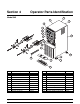
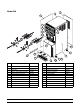
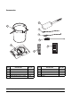
Figure 8
Item
Description
1 Control Switch
2 Liquid Crystal Display
3 Keypad- Left
4 Keypad- Right
5 Product Light- Left Side
6 Product Light- Right Side
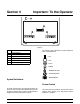
Symbol Definitions
To better communicate in the International arena, the
words on many of our operator switches and keys have
symbols to indicate their functions. The Model 349 is
designed with these International symbols.
The following chart identifies the symbol definitions
used on the Model 349.
=ON
=OFF
=AUTO
=PRIME
= BEATER MOTOR
= ALARM SILENCE
= MENU/SELECT
Control Switch
The control switch is located on the top of the control
channel. When placed in the ON position, allows
Slushtecht operation.